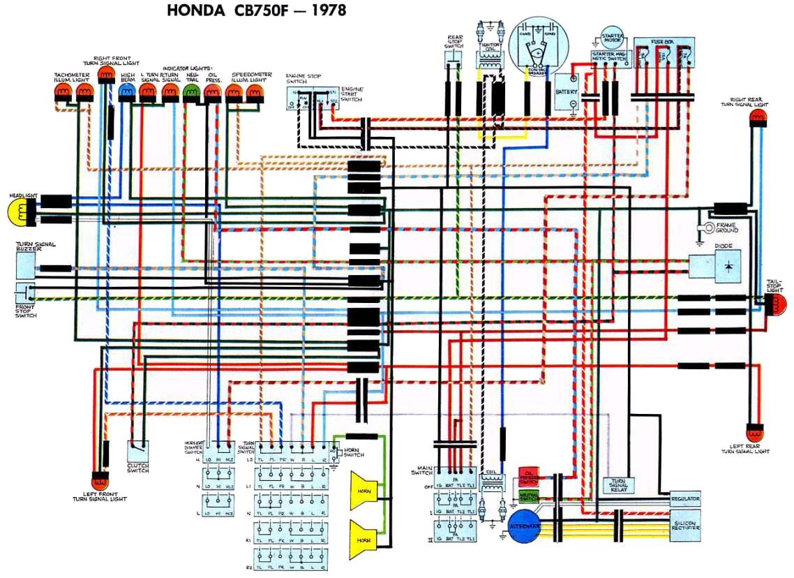
Page 1 of 2 wiring in an indicator buzzer. Trailer turn indicator lamps should flash in unison with vehicle indicator lamps and audible sensor should buzz.
_schematic.jpg)
Indicator Kits Without Lamps
Trailer indicator buzzer wiring diagram. Ensure that there is a good clean earth connection to the vehicle body the 7 pin socket the trailer 7 pin plug and the trailer lamp units. 4 pin trailer wiring diagram. Posted in problems questions and technical. This is often overlooked when booking a towbar or can be difficult to understand exactly what your vehicle requires if you have none or very little knowledge. This is either with a flasher unit or with a frequency control unit incorporated into the central electrics. Adding buzzer in the indicator of your motor cycle is very importantit increases the road safety many timesinstalling a buzzer in your motorcycle is very easyyou just have to search the.
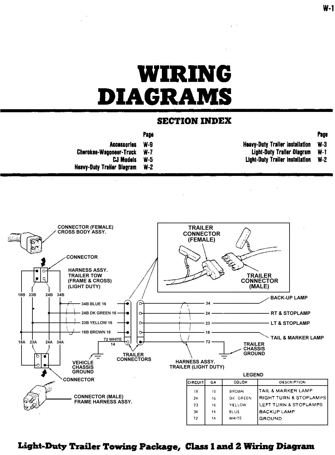
Check all wiring and if correct replace any fuses removed connect trailer plug and check vehicle and trailer lights function correctly. The trailer wiring diagram shows this wire going to all the lights and brakes. This is the standard uk wiring of a the normal socket and plug otherwise known as 12n. Some trailer builders just connect this wire to the frame then connect the ground from all the other lights and accessories to the frame as well. Note that this type of 4 pin connector is less common that 4 pin flat connector. Also it must connect with things if included that use the aux power and back up lights too.
The diagram below shows the view from outside the vehicle socket under the flap and from inside the trailer or caravan plug. Trailer wiring diagrams trailer wiring connectors various connectors are available from four to seven pins that allow for the transfer of power for the lighting as well as auxiliary functions such as an electric trailer brake controller backup lights or a 12v power supply for a winch or interior. Wiring diagram for self switching relay on 12s socket. Wiring diagram for double relay on 12s socket. Above we have describes the main types of trailer wiring diagrams. Wiring diagrams an important aspect of towbar fitting is the wiring which is required to power either your trailer lights or caravan internal electrics.
Check and test the fuses on all circuits. Attach the audible sensor to the vehicle wiring making sure not to cover the sound output hole. This type of connector is normally found on utvs atvs and trailers that do not have their own braking system. Im going to fit a small 12v buzzer into my indicator circuit to remind me to cancel my indicators. Towbar buzzer wiring diagram. With many modern cars it is best to take power from a source such as the bus bars at the back of the fusebox.
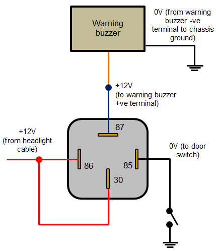
Below is the generic schematic of how the wiring goes. Before i try and fathom where to put it using a wiring diagram though does anybody know where the most obvious place would be to put it in the indicator circuit.


