Valid range for this output is 00 to 50 volts in 1 volt increments. Lingenfelter performance engineering 10564 views.

Connected Utilities Field Area Network 2 0 Design And
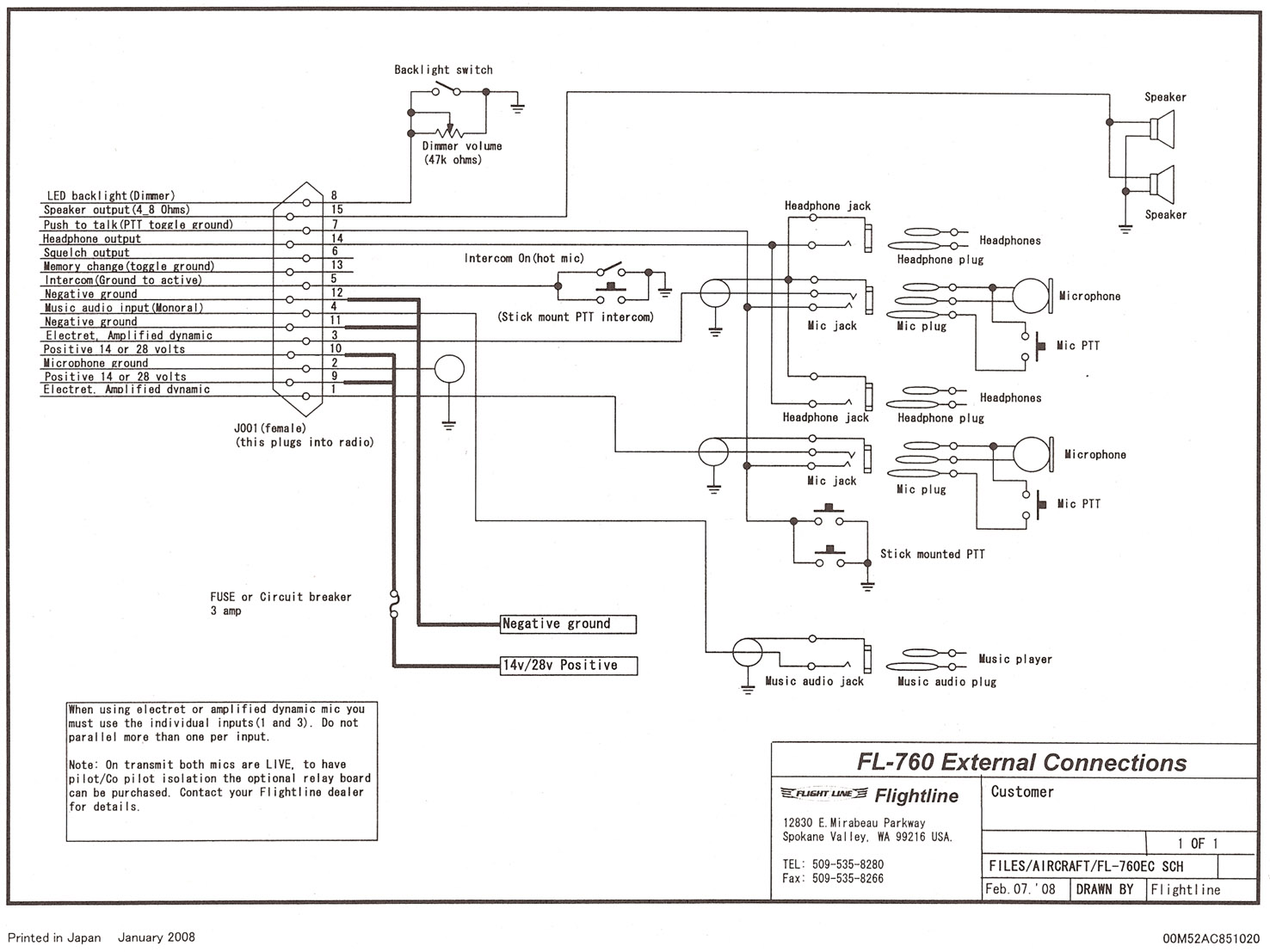
Nms 1000 wiring diagram. Card readers connect to tb5 of the n 1000 iii as shown here. Engine parts swingarms nitrous turbo kits chain sprockets air shifters exhaust kits and much more. This output will be at 00 volt when the nms 1000 is not activated. Instructions wiring manuals. To get to the download click add to cart nothing with show that its added to your cart then continue to checkout then complete order and it will be on the next page that shows up. On the n 1000 iv the card readers connect to the four reader board.
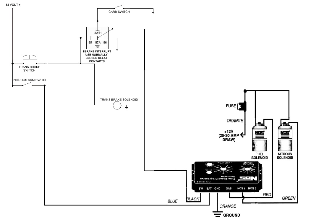
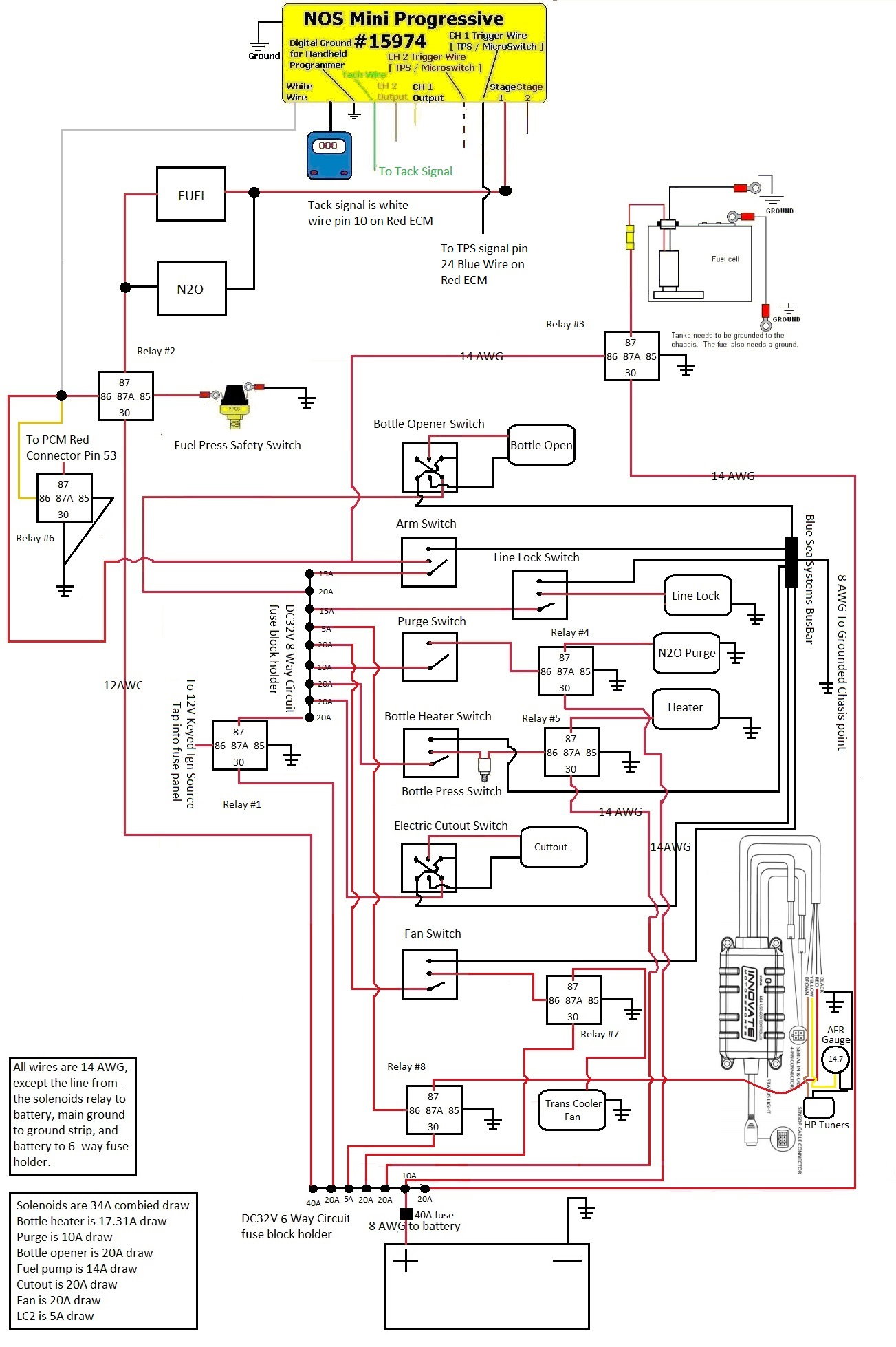
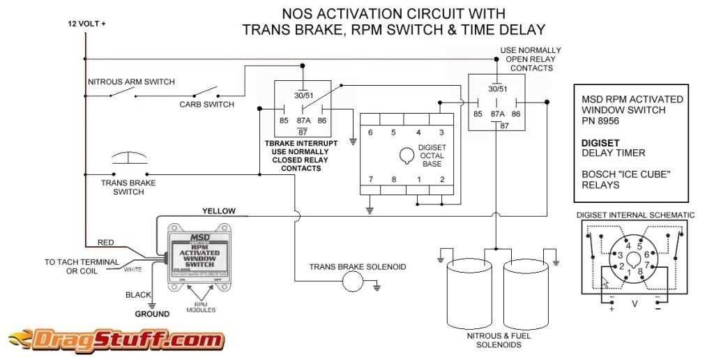
Resume start percent this setting determines the percent the nitrous resumes at if the user has to lift the throttle during activation. Refer to section 4 3 for typical wiring diagram. No laptop is needed and an easy to use user interface is built in. Your email address will not be published. Installation instructions wiring diagram ground activation connecting to the analog output connecting a wideband. Lpe ncc 001 nitrous control center coupled with our lnc 2000 for timing retard duration.
Wiring diagram ground activation page 18 connecting to the analog output page 19 connecting a wideband controller to analog in page 19 warranty information warranty page 19. Importantthe data must be erased to log new data and the power to the nms 1000 must remain on for 20 seconds after activation in order for the logged data to be saved. We revolutionized boost control with the ams 1000 and now plan on doing the same with the nms 1000 nitrous controller. Required fields are marked. Looks almost identical to the ams 1000. Schnitz racing has all the motorcycle performance parts you need to stay in front.
Caution do not submerge controller in liquid or directly wash unit with liquid of any type. 12 9 4 in. About nms 1000 this selection displays the current operating system version and the software build date. There are no reviews yet. Nms 1000 nitrous management system instruction manual pdf. Nms 1000 nitrous management system instruction manual pdf.
17 wiring diagram 12 volt activation important the nms 1000 must remain on even when the nitrous arming switch is off in order for the data logging function to work correctly. The nms 1000 nitrous controller contains high frequency digital electronics and will not function correctly without suppression wires. Be the first to review progressive nitrous controller nms 1000 nlr cancel reply.


