This telephone wiring diagram with photos and instructions will show you the direct steps to correctly wiring a telephone jack. A wiring diagram is an easy aesthetic depiction of the physical connections as well as physical layout of an electrical system or circuit.

Kestner Eng Co Ltd Contract No Manualzz
Nello one wiring diagram. A wiring diagram is used to represent how the circuit generally appears. The hot and neutral terminals on each fixture are spliced with a pigtail to the circuit wires which then continue on to the next light. Front view with closed casing 2. This diagram illustrates wiring for one switch to control 2 or more lights. What is a wiring diagram. Wiring diagrams show components mounted in their general location with connecting wires.
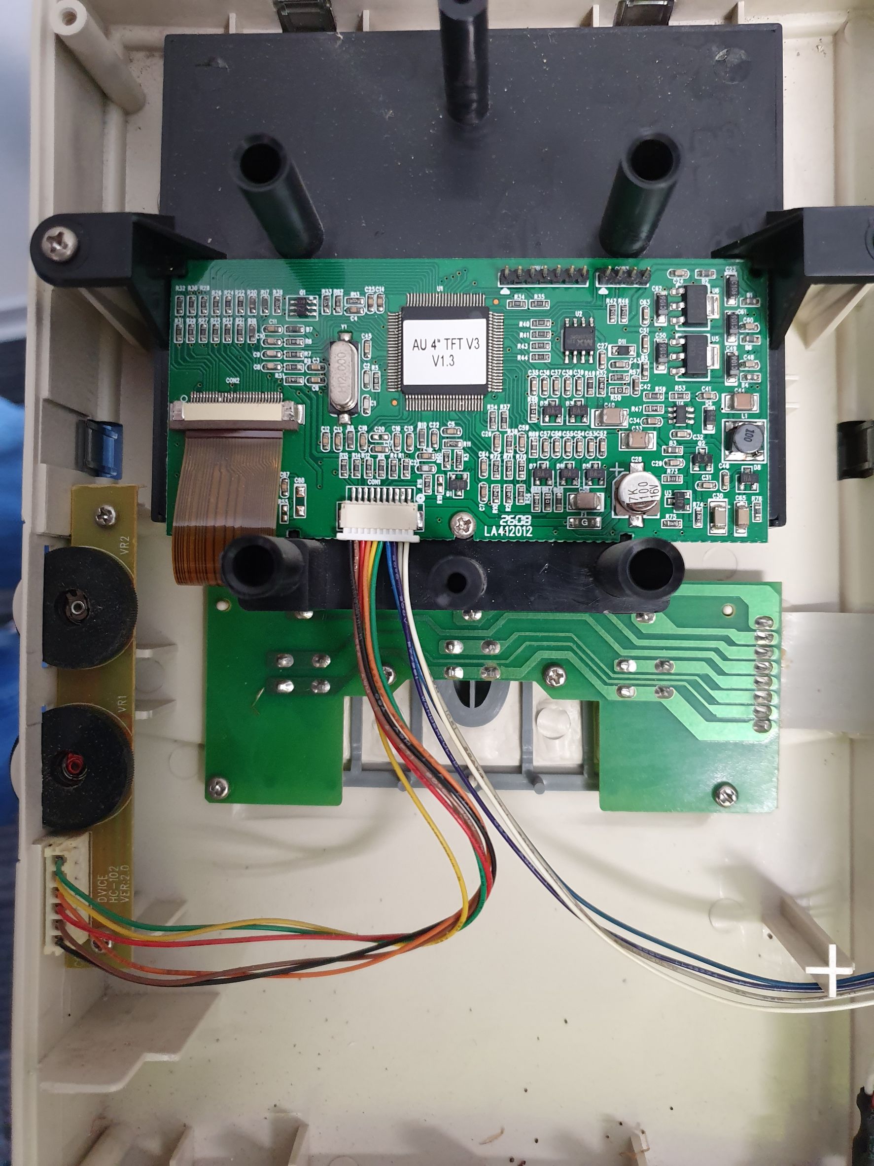
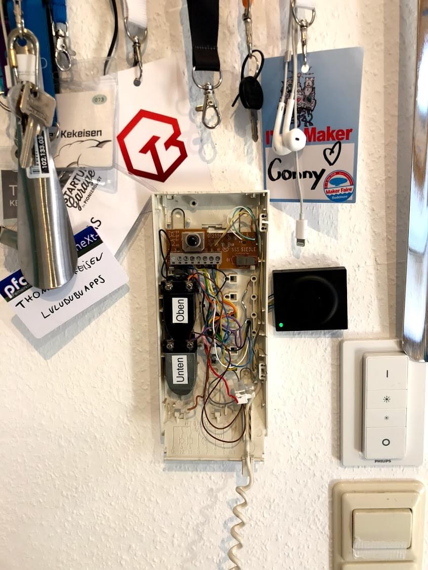
Multiple light wiring diagram. When as well as how you can use a. With open casing and 3. These units can process up to a million lines of code which is more than some jet fighter. A close up view of the circuit board wiring which should be as sharp as possible so that you can read all numbers. All car amplifier will work with a 4 ohm load wire it like this diagram.
To help illustrate the differences between wiring diagrams and schematics a basic control circuit will first be explained as a schematic and then shown as a wiring diagram. The power can come from either the switch box or the fixture box and a set of electrical switch wiring diagrams will explain each of these scenarios to you clearly. Nello is always looking for unknown intercom models. One winding tapped winding tapped winding two windings 3 2 1l1 t1 l2 t2 l3 t3 stop ol start 123 l1 l2 m 1 2 3 a1 a2. Wiring a telephone jack after installing the cat 3 3 pair phone wire i am ready to install the wall jack. Wiring diagram since wiring connections and terminal markings are shown this type of diagram is helpful when wiring the.
For the identification of your model the following three photos are most helpful for our engineers. It reveals just how the electric cables are adjoined and also could additionally reveal where fixtures and parts may be attached to the system. Single pole may sound simple but there are different ways to wire a single pole switch. Switch wiring diagrams a single switch provides switching from one location only. Electronic systems in modern cars and trucks have on average 30 electronic control units ecus and luxury cars have even more as many as 100 ecus. 3ø wiring diagrams 1ø wiring diagrams diagram er9 m 3 1 5 9 3 7 11 low speed high speed u1 v1 w1 w2 u2 v2 tk tk thermal overloads two speed stardelta motor switch m 3 0 10v 20v 415v ac 4 20ma outp uts diagram ic2 m 1 240v ac 0 10v outp ut diagram ic3 m 1 0 10v 4 20ma 240v ac outp uts these diagrams are current at the time of publication.
Interactive wiring diagrams mitchell 1 re invents the wiring diagram again. When you only wire one of a dual voice coil subs coils you split its power handling ability in half threatening to burn the sub out and increase its distortion because the sub has to push around the dead weight of the disconnected coil. The source is at sw1 and 2 wire cable runs from there to the fixtures.


