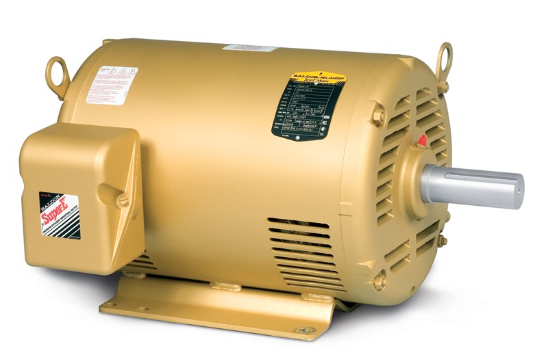
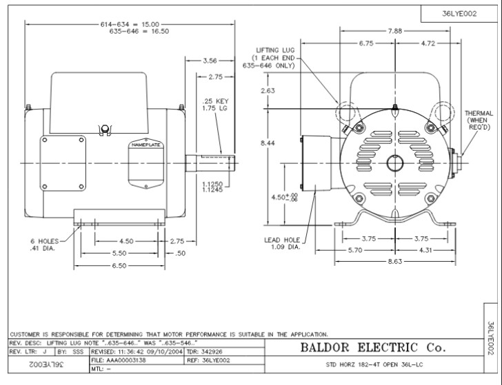
If not the arrangement will not function as it should be. How to wire a baldor 3 phase motor.

Gv 1724 Baldor 10 Hp Motor Capacitor Wiring Diagram
Baldor motors wiring diagram. Baldor motor wiring diagram baldor 5hp motor wiring diagram baldor brake motor wiring diagram baldor dc motor wiring diagram every electrical structure is composed of various diverse parts. Baldor motor capacitor wiring diagram what is a wiring diagram. It shows the elements of the circuit as streamlined shapes as well as the power and signal links in between the tools. Each component should be set and connected with different parts in particular way. Yet with the help of this step by step guide this task will be become as easy as counting to five. A wiring diagram is a streamlined traditional photographic depiction of an electrical circuit.
Variety of baldor motors wiring diagram. It contains guidelines and diagrams for various kinds of wiring techniques as well as other products like lights home windows etc. Customer acknowledges and agrees that for abb software or for abb services comprised of data information analyses estimates output or models collectively information such information is based upon customers data. Collection of baldor single phase motor wiring diagram. You need to refer to the individual plate for your particular electric motor when wiring it as wiring procedures may be different particularly between ac and dc motors. Wiring a baldor motor can at first glance look to be a very intimidating task.
Each component ought to be placed and linked to different parts in particular manner. Each type of baldor electric motor has labeled wiring diagrams on a plate fixed on the motor. Baldor motor wiring diagrams 3 phase 9 wire e26 diagram 27cb48 3 phase baldor motor wiring diagrams library xc 2461 baldor motor wiring diagrams 3 phase xd 4058 reliance motor diagram free wiring baldor motor wiring diagrams 3 phase 9 wire e26 diagram 27cb48 3 phase baldor motor wiring diagrams library xc 2461 baldor motor wiring diagrams 3. It reveals the parts of the circuit as simplified shapes as well as the power and also signal connections between the tools. A wiring diagram is a simple visual representation from the physical connections and physical layout associated with an electrical system or circuit. Now for the purposes.
Single phase motor wiring diagram with capacitor baldor single phase motor wiring diagram with capacitor single phase fan motor wiring diagram with capacitor single phase motor connection diagram with capacitor every electrical arrangement is made up of various unique pieces. A wiring diagram is a simplified conventional photographic depiction of an electrical circuit. 115 volt ac motor wiring wiring diagrams thumbs baldor motor wiring diagram wiring diagram contains many in depth illustrations that show the link of assorted items.


