This designation will be needed to determine the correct brake wiring diagram in the following sections of this guide. A wiring diagram is a simplified conventional photographic depiction of an electric circuit.
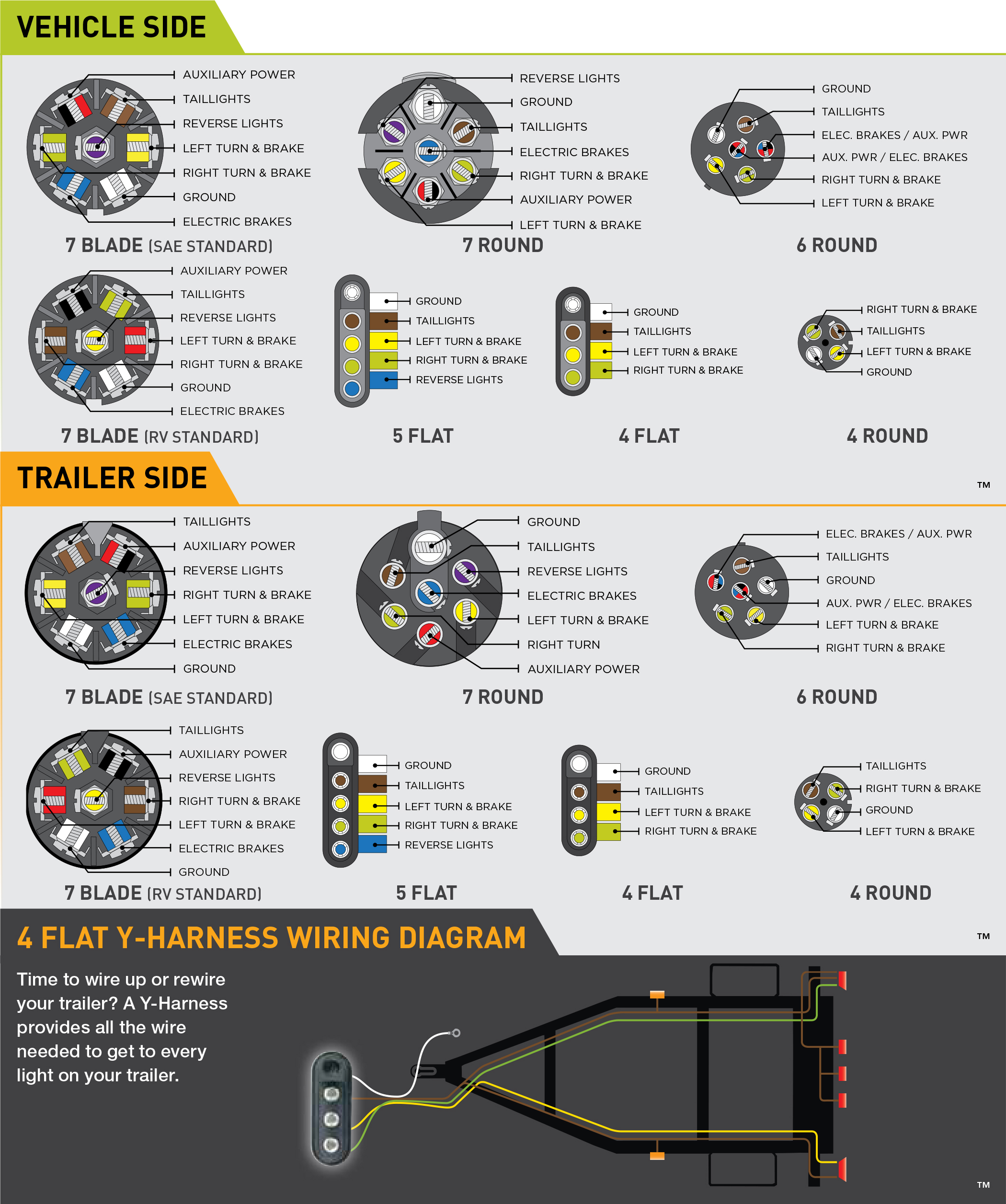
Trailer Connector Pigtail Replacement Amp General Trailer
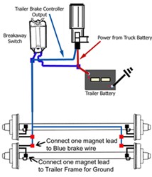
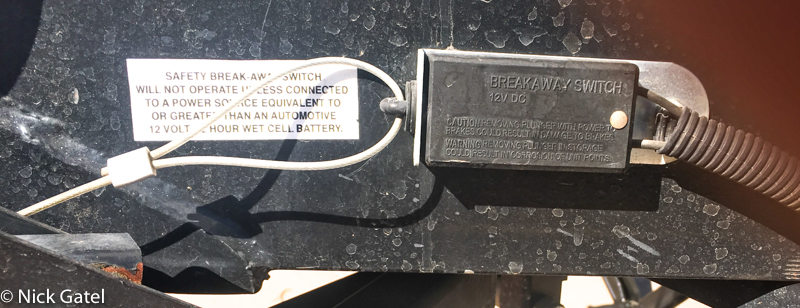
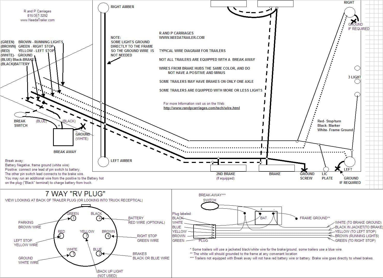
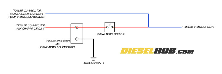
Break away brakes wiring diagram. Noteblue wires are interchangeable on the break away switch. This car is designed not just to travel one place to another but also to take heavy loads. 3 brake voltage lists the brake voltage required to operate the brake. Break away systems may be added to the service brake circuit. Variety of trailer breakaway wiring schematic. 4 brake control lists the brake control type.
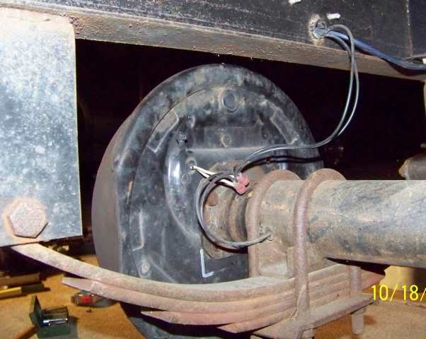
Brake light wiring diagram this brake light wiring diagram gives you a clear picture of where each wire goes. Ensure it is sealed off and cannot. Elecbrakes is designed to operate 1 to 2 braked axles. Connect other blue wire of break away switch to the blue wire labeled brake from the break away box b. Visit howstuffworks to check out this brake light wiring diagram. It shows the components of the circuit as streamlined shapes and the power and also signal connections in between the devices.
Trailer breakaway wiring diagram 3 wire trailer breakaway switch wiring diagram hopkins trailer breakaway wiring diagram rv trailer breakaway switch wiring diagram people today understand that trailer is a vehicle comprised of quite complicated mechanics. Bg bge bsr etc. The service brake circuit must be disconnected from an existing trailer plug. These maybe followed by additional characters. Splice one blue wire of the break away switch to the electric brake wire coming from the trailer side connector a see diagram on next page. Elecbrakes must be connected to trailer wiring circuits as outlined in the wiring diagram.
