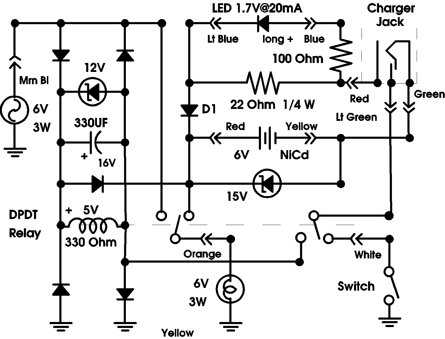
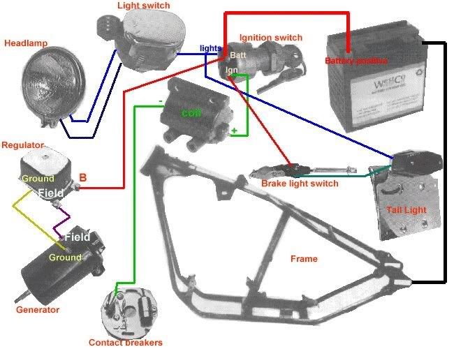
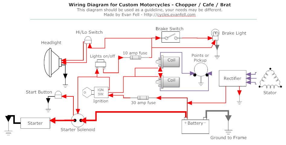
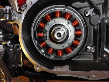
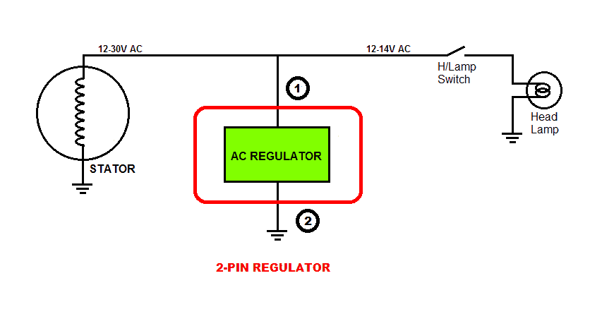
Collection of cycle electric generator wiring diagram. 6 volt conversion see notes 2 3 the l model can be used with any battery.
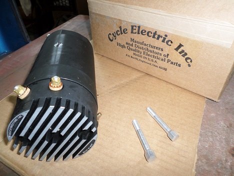
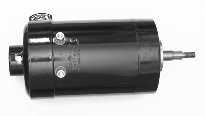
Harley Generator Repair Or Replace
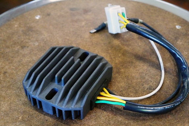
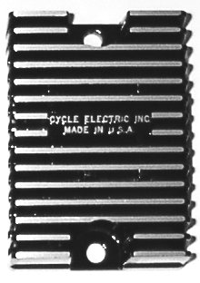
Cycle electric regulator wiring diagram. Motorcycle electric products and accessories motorcycle fuse boxs bullet terminals spade terminals and connectors adhesive lined dual wall shrink tube headlight relay kits horn relay kits auxiliary. If you plan to ride it use a high quality electronic regulator and hide it. All cycle electric inc regulators are built to lastwe start with a rugged design capable of handling overloads and continuous operation. We manufacture all of our generators regulators rectifying regulators and stators in our brookville ohio factory. Assembly process to ensure a low failure rate and the longest service life. Dgv 5000 for 1936 1984 12 volt systems with 7 amps or larger battery.
See note 1 dgv 5000 l for 1936 1964 12 volt systems with small 12 volt battery in 6 volt oil tank. Start at the offending turn signals and find out what color wires go to them. Dgv 2569 dgv 2578 dgv 5000 dgv 5000l dgv 5006 in 2569 in 2578 in 5000 in5006. The schematic is rather easy to understand. Let the road you chose to ride bring you happiness karl s fahringer president cycle electric inc. Cycle terminal we have your wiring needs.
It reveals the parts of the circuit as streamlined forms and the power and also signal links in between the gadgets. Then we use only top quality materials and military spec. Oem style japanese motorcycle wiring terminals and connectors for yamaha kawasaki suzuki and honda motorcycles from the 60s to the 90s. Look for the hot wire going to the turn signals. Cycle electric inc dgv 5000 series installation instructions. You can take the guts out of a mechanical regulator month it in the stock position and use it as a junction block for your wire connections.
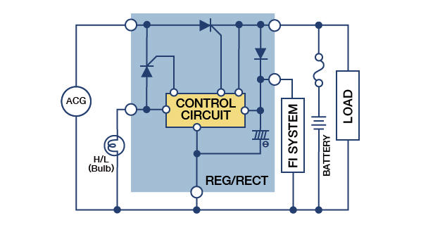
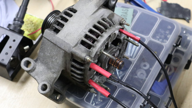
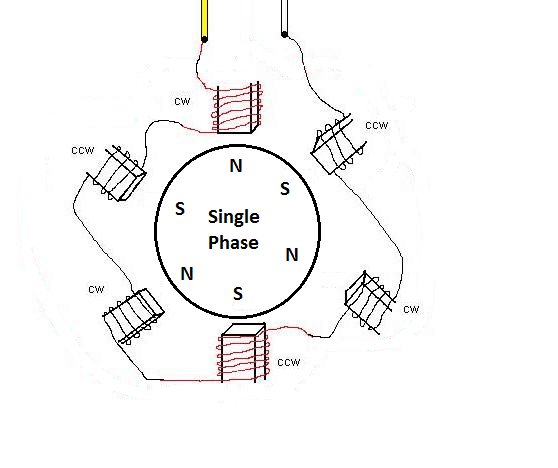
Cycle electric inc is the leading manufacturer of high quality american made charging systems for use on harley davison and other american made v twin motorcycles. The 3 phase output from the alternator is sequentially applied across three power transistors which basically act like shunting devices for the alternator current. If the turn signals dont work and the lights do you do not need to test the lights. A wiring diagram is a simplified standard photographic representation of an electric circuit. If all looks ok get out your wiring diagram and find out what color wires you need to test. The proposed 3 phase motorcycle voltage regulator circuit for motorcycle may be witnessed in the diagram below.


