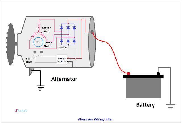
Wilson alternator wiring diagram wilson alternator wiring diagram wilson alternator wiring diagram every electrical arrangement consists of various distinct components. There are three types of searches possible depending on whether you know the exact part number needed or if you are trying to determine the correct one from incomplete information.
Wilson Alternators
Wilson alternator wiring diagram. Note for marine unit use 90 01 3103 42 amp. Note for unit with 24 volt 1 wire hookup use 90 01 3102 40 amp. Otherwise the structure will not work as it ought to be. Note for unit with debris shield fan and pulley use 90 01 4437. Choose the desired type by clicking the round radio button next to the name. As like our remanufactured units every new alternator is tested prior to leaving our facility.
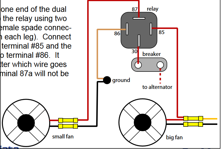
Our alternators are manufactured using 100 new premium parts and are tested to meet or exceed oe standards. Wiring diagram for wilson alternator. And connect the red wire to the output side of the alternator 1032 stud take the long wire and connect to the side of the coil. Note this 63a alternator is used to replace all lower amp units. New wilson alternators are designed for customers who demand the reliability and performance we have proven on our remanufactured offerings. Note for enclosed unit use 90 01 3078 18 amp.
8774804034 m f 700 700 cst more details. Note for niehoff use 90 07 1052 80 amp. Each part ought to be set and connected with different parts in specific manner. Need to know which wires connect to the 1 and 2 terminals for control wires. Posted by 4xpaddlers on oct 14 2010. The part search function searches against both wilson and cross reference part numbers.


