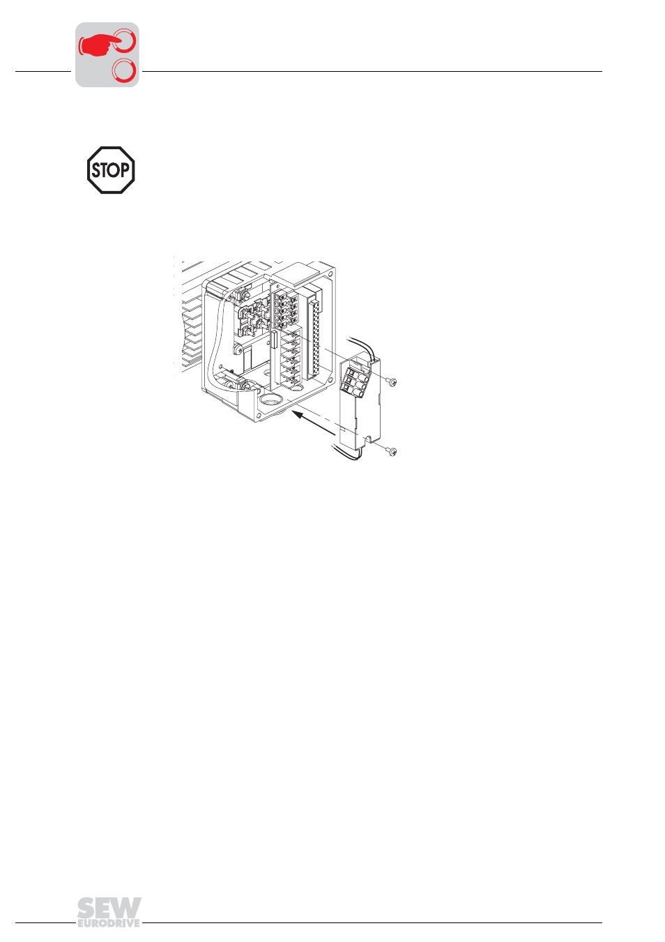
Motors 2 encoder cable comparison movidrive mdx 61b dtdv. 4 data sheet encoder and encoder cable comparison dt.
.jpg)
Diagram Logic Diagram Encoder Full Version Hd Quality
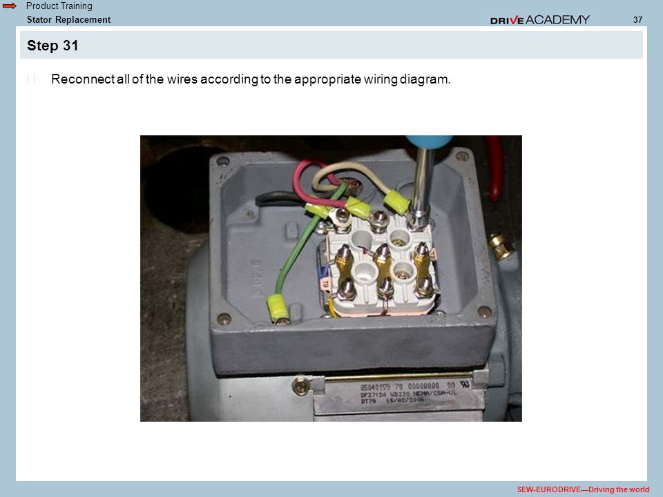
Sew eurodrive wiring diagram. In addition they may be wired for either normal or rapid stopping. Drive engineering practical implementation. Usa diagram 10939p000007 l1 l2 l3 u1 v1 w1 t1 t2 t3 u5 t8 v5 t9 w5 t7 u2 v2 w2 t4 t5 t6 v6 t10 u6 t11 w6 t12 l1 l2 l3 u1 v1 w1 t1 t2 t3 u5 t8 v5 t9 w5 t7 u2 v2 w2 t4 t5 t6 v6 t10 u6 t11 w6 t12 two speed single winding low speed see motor nameplate high speed see motor nameplate connection dt33 diagram l1 l2 l3 l1 l2 l3 2u 2v 2w 1u 1v 1w t5 t1 t2 t3 t6 t4 2u 2v 2w 1u 1v 1w t5. Important notes 6 2018 common connection diagrams 24 brake control sew brakes are available for either normal or rapid starting. Dr71 315 drn80 315 ac motors for increased vibration stress level 1. Wiring diagrams brake rectifiers and coil data.
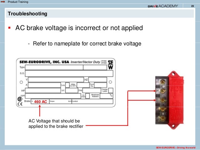
The bmk brake control system optional for frame sizes 71 to 225 the bmk rectifier functions like the rectifier type bge. Back to top. Brake voltage matches low. Sew eurodrive is a leading company in the field of drive engineering. A single speed motor the motor is started and run across the line and the brake voltage. Determine the correct brake wiring diagram in the following sections of this guide.
2010 dr motor common connection diagrams 3 table of contents. Common connection diagrams edition 062010 9pd0058 us. Motors 2 meaning of the symbols encoder cable comparison movidrive mdx 61b dtdv. A wiring diagram is a simplified standard pictorial representation of an electrical circuit. Gear units r7 f7 k7 s7 series spiroplan w operating instructions cm synchronous servomotors. The range of products offered includes gearmotors frequency inverters and drive solutions from one source.
It shows the parts of the circuit as simplified forms and the power as well as signal links in between the devices. Assortment of sew eurodrive motors wiring diagram. Dr71j dr100j ac motors with lspm technology. Ac motors dr71 225 315 operating instructions. Motors common connection diagrams. The brake can be wired to the motor terminal block under the following conditions.
Connection diagram dt13 examples motor voltages. 200 346y volts 60 hz 330 575y volts 60 hz 220 380y volts 50 hz 1 motor wired for low voltage.




.jpg)
