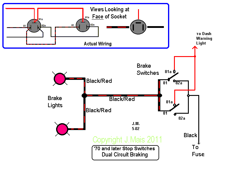
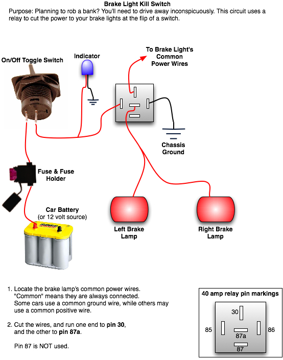
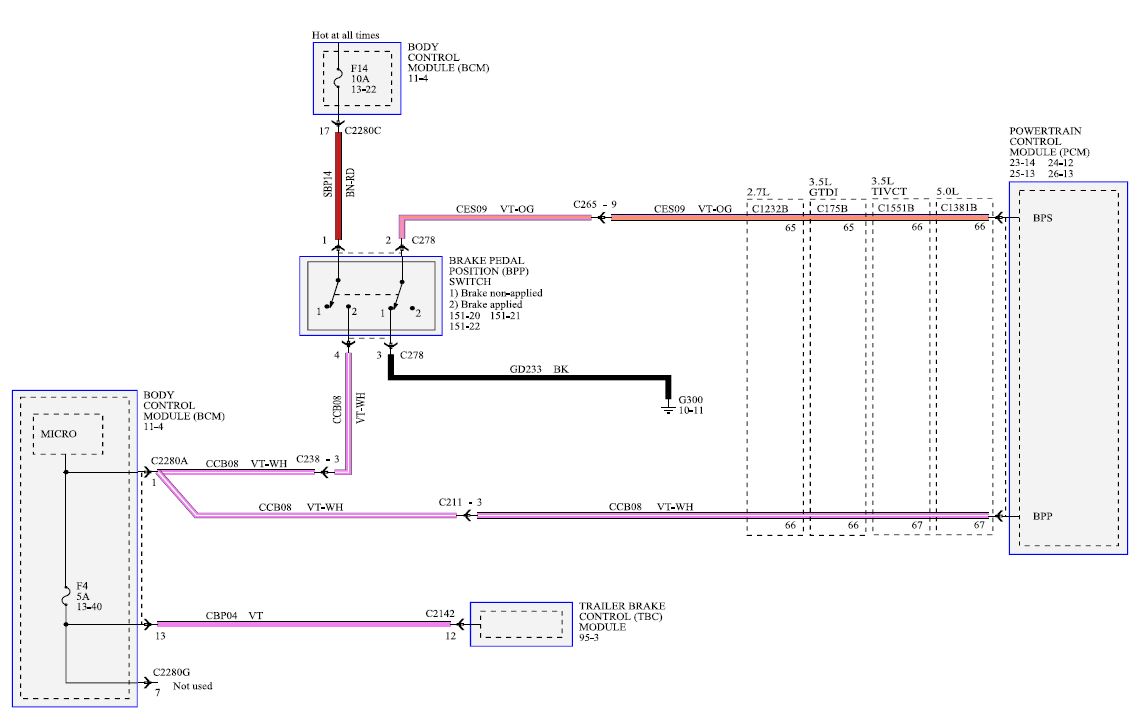
At the other end is the brake switch where the pedal presses down and creates contact that completes the circuit. The system draws power from the cars battery.
1990 F250 Brake Light Problem Ford Truck Enthusiasts Forums
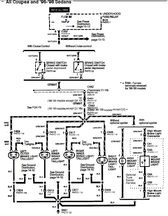
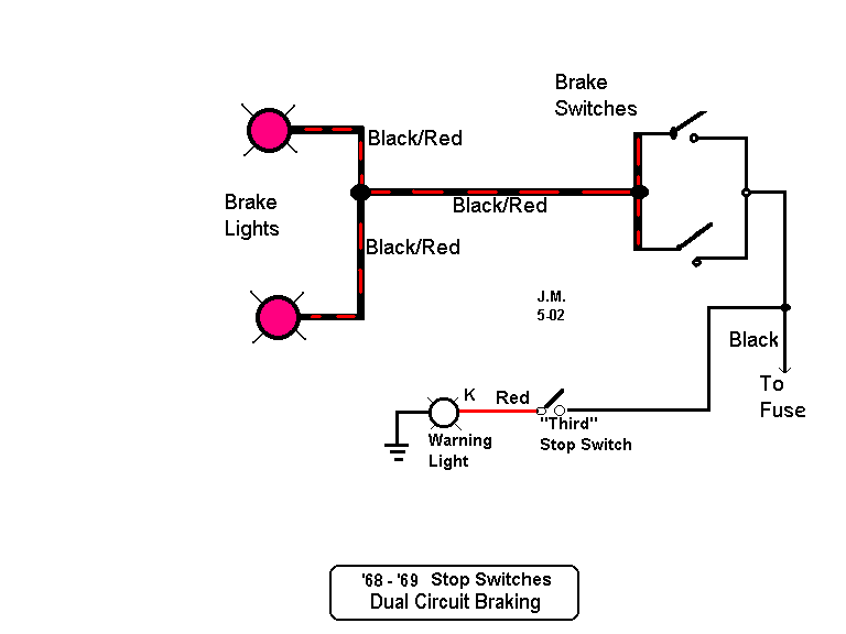
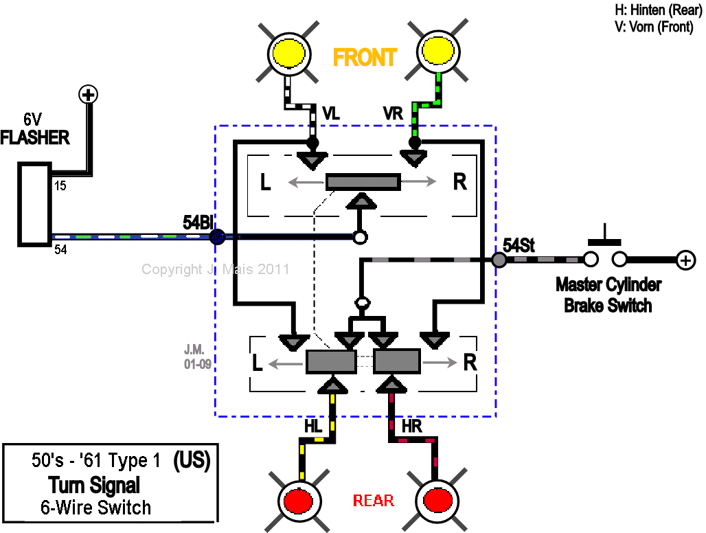
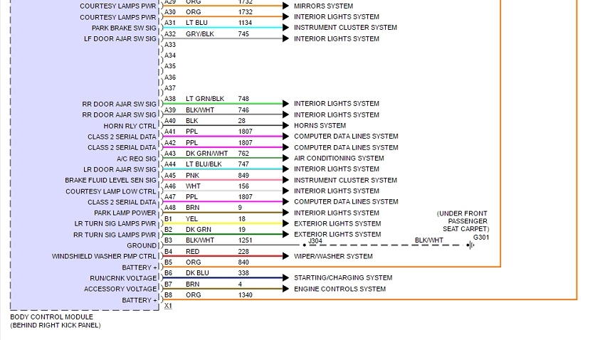
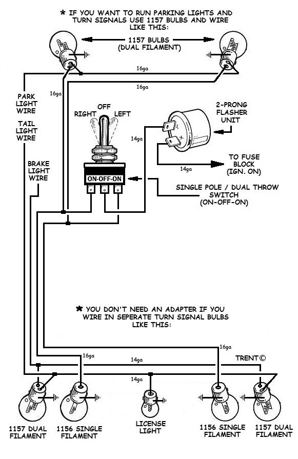
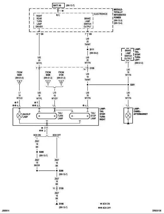
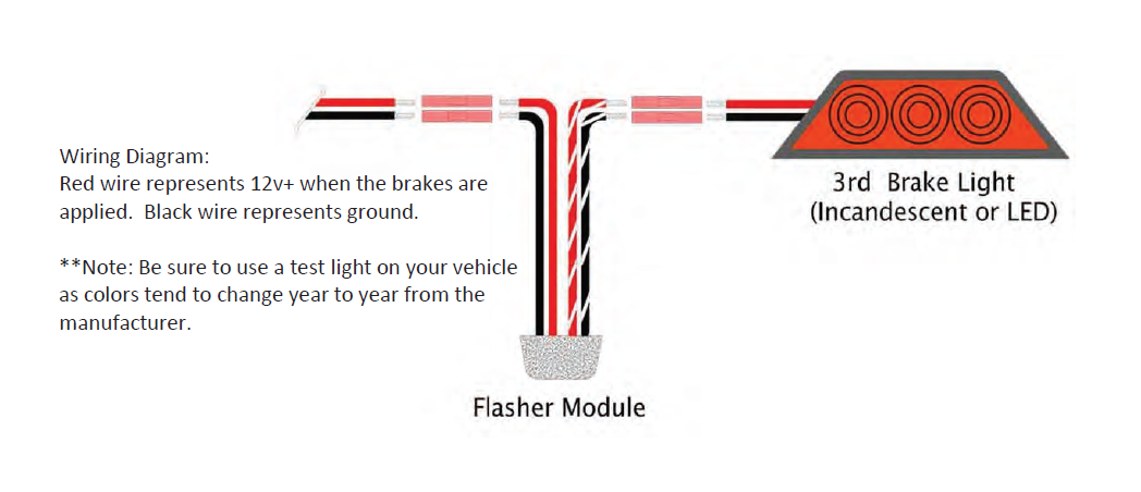
Brake light wiring diagram. Assortment of third brake light wiring diagram. The brake light wiring system in most cars is not overly complex. Also it must connect with things if included that use the aux power and back up lights too. Some trailer builders just connect this wire to the frame then connect the ground from all the other lights and accessories to the frame as well. The switch itself is connected with a plug so you may need to splice your power wire to the power wire coming out of the plug. It shows the parts of the circuit as simplified shapes as well as the power and signal connections in between the gadgets.
Once the switch has power you need to connect the output wire from the switch to the rest of the brake light wiring harness. The trailer wiring diagram shows this wire going to all the lights and brakes. At one end you have the lights themselves. Well the first third brake light i installed i had to pull a wire from the third brake light all the way underneath the carpet to the brake pedal switch and i thought it would be easier to pluck the signal of both brakelights via the trunkbench test your circuit first and apply power to the circuit with the brakelight connected for at least. Bulbs in sockets connected to a wiring harness. A wiring diagram for your specific vehicle will show you which wire in the bundle to splice.
Visit howstuffworks to check out this brake light wiring diagram. Brake light wiring diagram this brake light wiring diagram gives you a clear picture of where each wire goes. A wiring diagram is a streamlined conventional photographic depiction of an electric circuit.
