Posted march 28 2011. Turn the ignition switch to the off position.
Alfa Rally Computers Small Systems Specialists
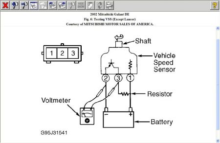
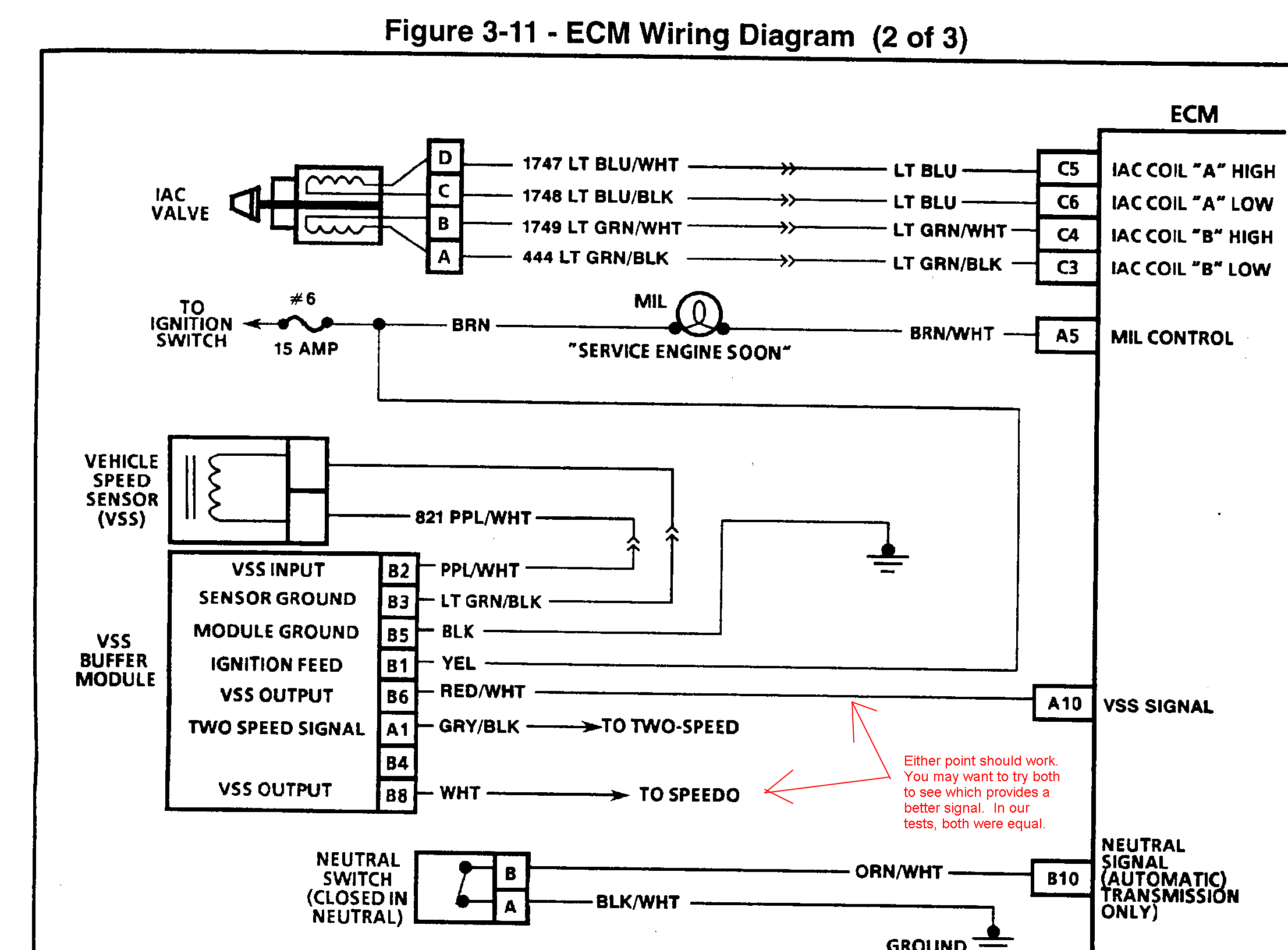
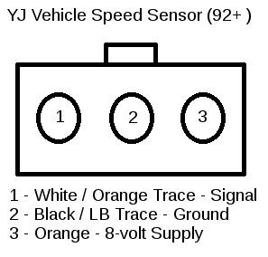
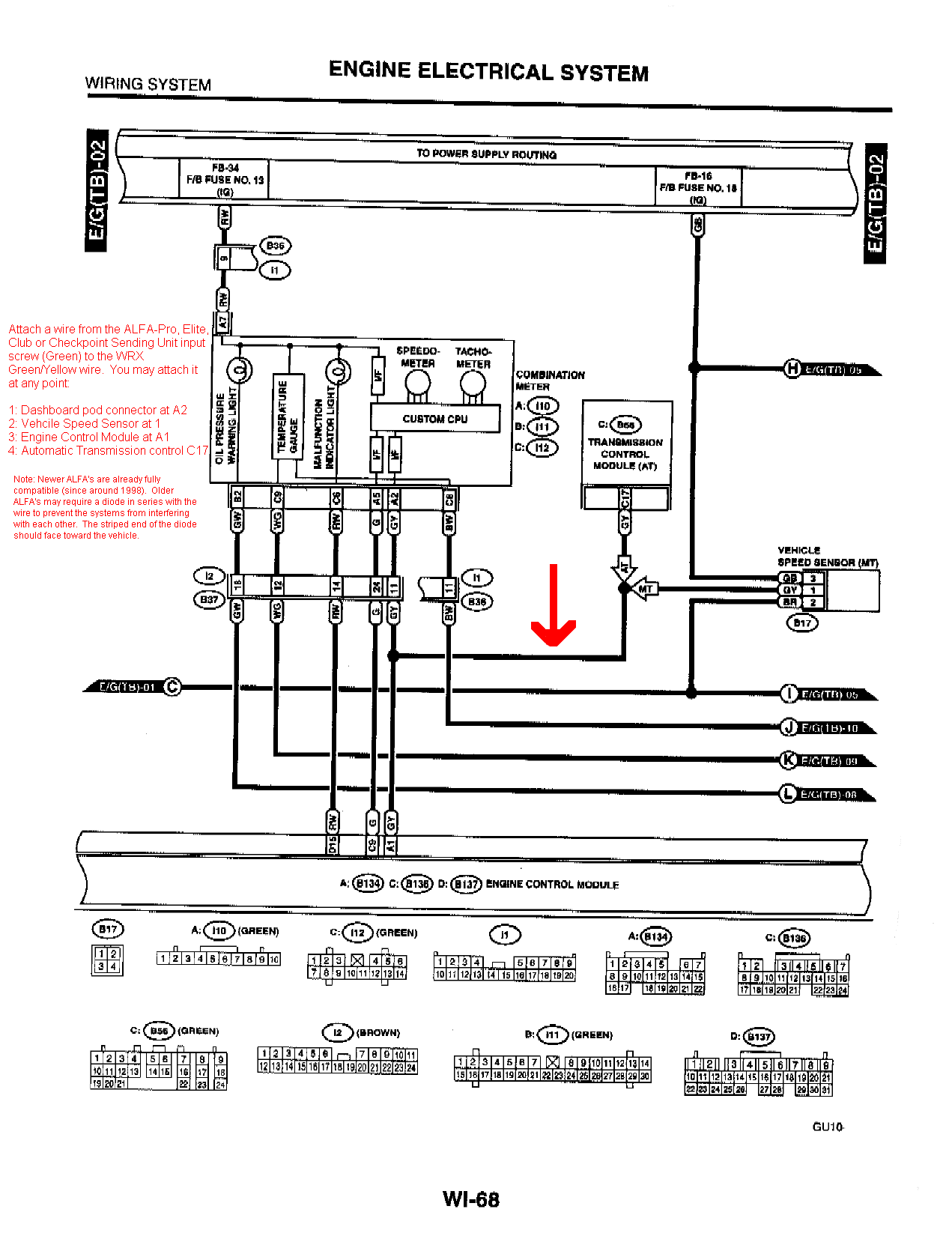
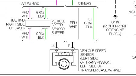
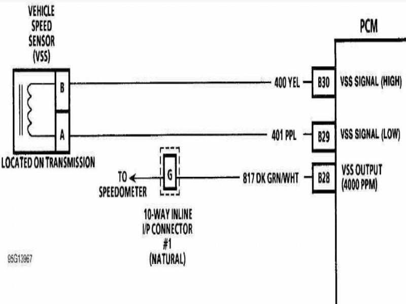
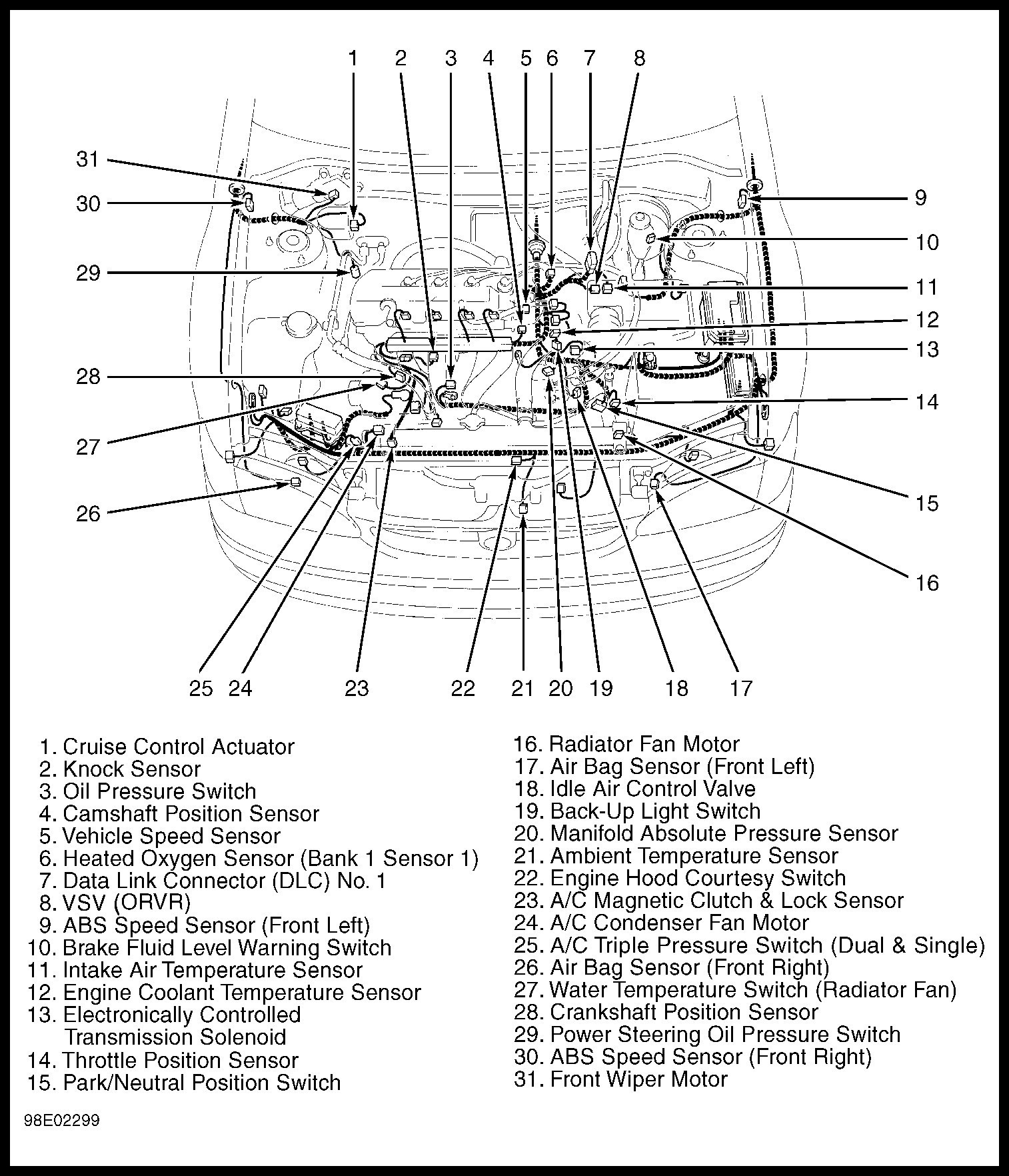
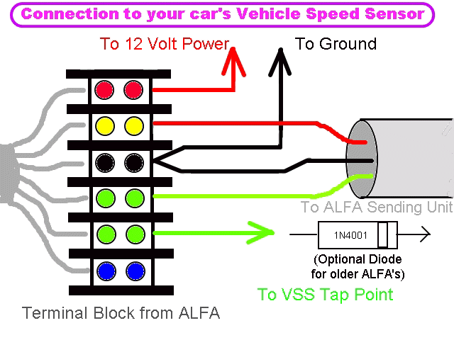
Vehicle speed sensor wiring diagram. Vehicle speed sensor replacement. If you are intending on testing the vehicle you will actually have to drive the wheels with the engine to obtain sufficient rpms to generate a signal. Follow your speedometer manufacturers recommendation for wiring connections. The function of the input shaft speed sensor is to keep track of. Vehicle speed sensor wire location. You will actually find two speed sensors in the transmission of each new vehicle out today.
Hamilton318 0 hamilton318 0 enthusiast. A pulse compensatorconverter unit may be. Some aftermarket wiring harnesses dont use a vssthey simply ground the pn parkneutral wire so that the ecm. Disengage the wiring harness connector from the vss. Tremec electronic speed sensor info vss posted on july 2 2019 july 3 2019. Before stealth conversions began offering aftermarket vehicle speed sensors for engine swaps in 1991 the biggest obstacle for most people who installed the tpitbi engines into their vehicles was the vss vehicle speed sensor.
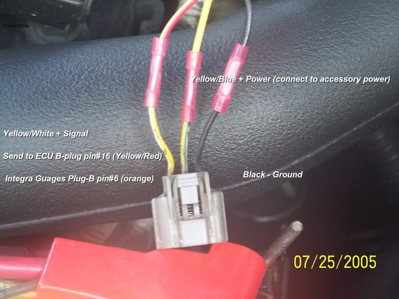
One speed sensor is called the input shaft speed sensor and the other is the output shaft speed sensor. If the resistance is 190250 ohms the sensor is okay. I installed a navigation system in my truck over the weekend but am having a bit of a problem. Since he is testing the 2 wire speed sensor while it is out of the vehicle he breaks out the high powered drive device a drill to spin the sensor at the necessary rpms to generate a signal. Both wires connect the vss to your vehicle to ground the sensor and transmit information about youre vehicles speed. Blue wire on most wiring diagrams and the one on the right toward the rear of car is the signal terminal yellow on most wiring diagrams.
While i am going down the. Vehicle speed sensor testing. By hamilton318 march 28 2011 in 1999 2013 silverado sierra 1500. These two sensors work together to relay information back to the engine control unit. Disengage the wiring harness connector from the vss. There are 2 wires connected to the vss a black one and a white one.
Using a digital volt ohmmeter dvom measure the resistance ohmmeter function between the sensor terminals.
