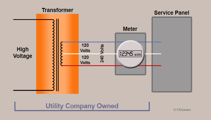
Wiring diagrams sometimes called main or construction diagrams show the actual connection points for the wires to the components and terminals of the controller. Note that these diagrams are without a barrier or isolator fuses and surge protector for keeping it very simple and understandable.
Model Railroad Wiring
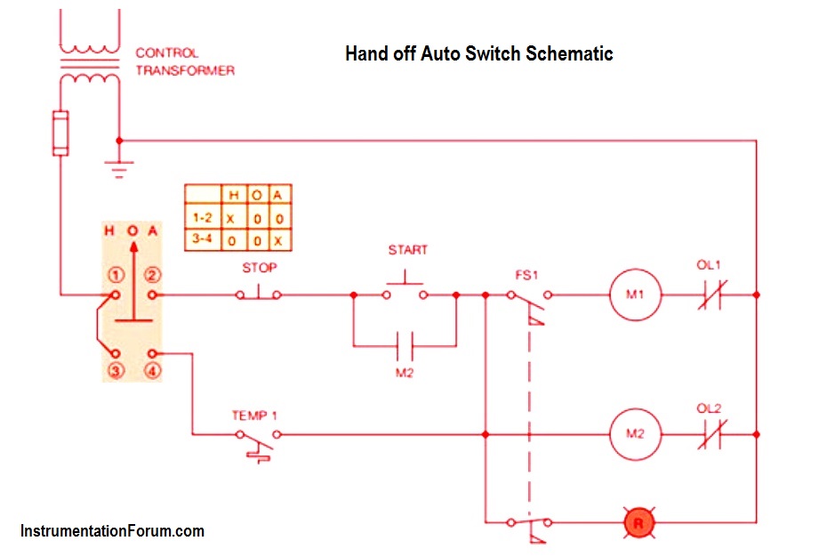
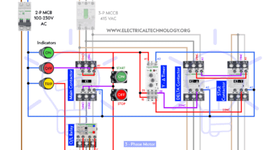
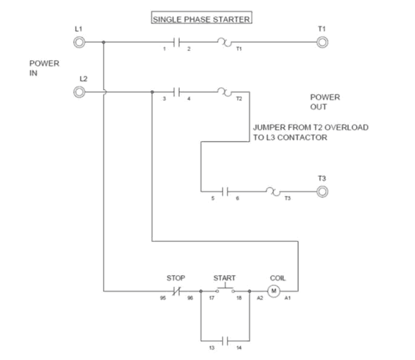
Local control station wiring diagram. I am here with giving you a vfd start stop wiring diagram for running a vfd through panel board push button and keypad of the vfd it is called hmi. I operation depressing the start button energizes coil m hold in contacts m and maintains the circuit after the start button is released. I zl ii i i ii i i fo 0. 2 motor start but only one at a time. 4 stop starts wiring. Wire per local electrical code using 78 diameter holes in bottom of control center cabinet and install nema 4 watertight electrical connectors not supplied.
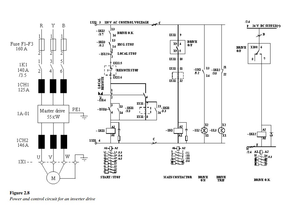
The wiring should be carried out in accordance with the layout shown in the ac and dc diagrams. They can be used as a guide when wiring the controller. Basic wiring for motor control technical data they show the relative location of the components. Vfd is a short form of variable frequency drive or variable voltage variable frequency drivethe vfds are working based on changing the input frequency and input voltage of the motor we can change the speed of the. Wiring diagrams show the interconnection of the multicore cables for example between the switchgear and the associated control panels and the routing of individual wires to the equipment installed in the relay and control panels. These diagrams are required to facilitate the wiring of the measurement protection and control equipment at the substation construction stage.
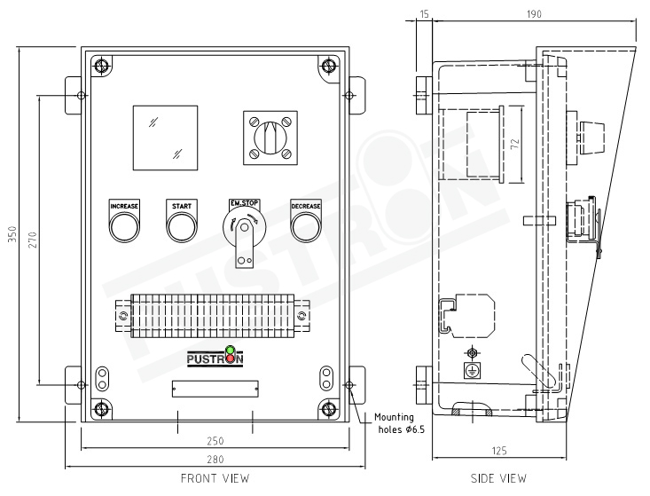
2 station motor control. Schematic drawing of control wiring usung push button. In this article we are sharing the basic concepts of plc and dcs control systems wiring diagrams for digital input di digital output do analog input ai and analog output ao signals. Ex e mb ib iic or ex tb iiic wiring diagram 1 lcp100 protection method lcp100 power source wiring order from logic solver dvc6200 sis mode current or voltage ex e mb ib iic ex tb iiic loop dvc6200 sis then lcp100 point to point 2 logic solver output 8 20 ma user supplied 1 notes. Replace disposer motor cover. Local control stations for electric actuators onoffjogproportional promation engineerings local control stations lcs give you the choice of using remote process control signals for the actuator or operating the actuator at the location of your choice either at the actuator or just nearby.
Wiring 2 push buttons in series. Typical wiring diagrams for pushbutton control stations start stop control wiring diagrams single station basic circuit r 1 klai. Vfd start stop wiring diagram. After completing the connections close door and lock. 1 j start 2 3 stop i no. Two push button connected in parallel.
Lcp100 local control panel may 2020 8 figure 5. 2 button start stop switch. Connect water solenoid valve as shown in the wiring diagrams on pages 7 8 9 and 10. 2 push start stop 3phase button connections. A single switch two wire multi drive starter.
Gallery of Local Control Station Wiring Diagram