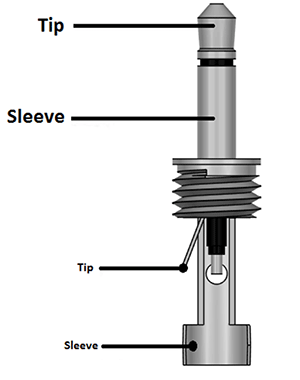
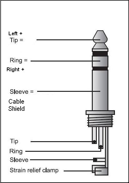
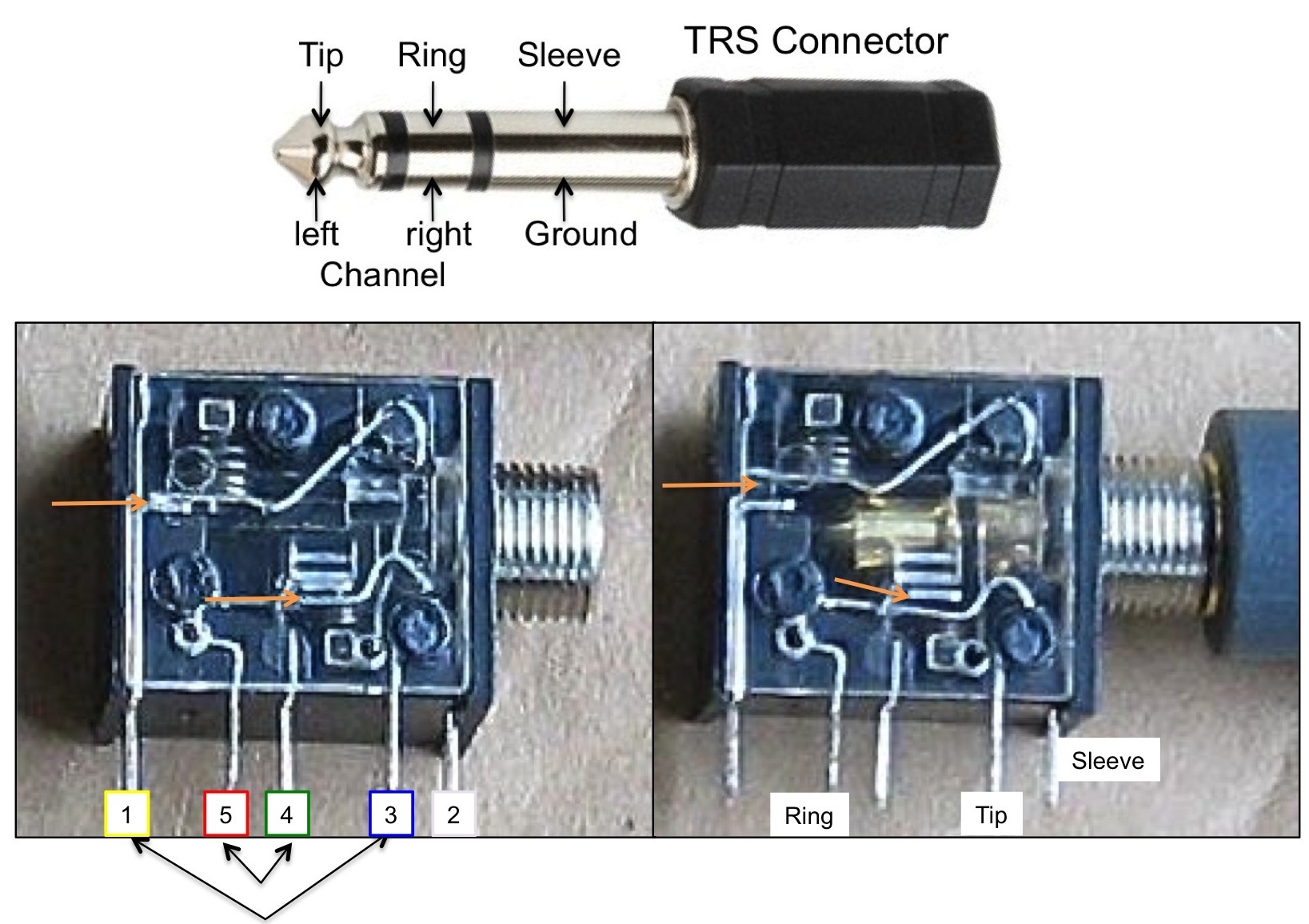
This e book even includes recommendations for extra provides that you might need as a way to end your tasks. The tip is the end of the plug the ring is the small middle section located between the two plastic dividers and the sleeve is the rest of the metal part of the plug.
Audeze 4 Pin Mini Xlr To Trs Wiring Help Headphone
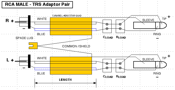
Trs female wiring diagram. Trs jack wiring diagram data wiring diagram today trs wiring diagram. To manufacture a pcb layout you must know the friends. A trs connector tip ring sleeve also called an audio jack phone jack phone plug jack plug stereo plug mini jack mini stereo or headphone jack is a common analog audio connectorit is cylindrical in shape typically with three contacts although sometimes with two a ts connector or four a trrs connector. Search for trs connector electrical wiring here and subscribe to this site trs connector electrical wiring read more. It was invented for use in telephone switchboards in the 20th century and. A stereotrs short for tipringsleeve 14 inch plug looks like an analog stereo headphone plug.
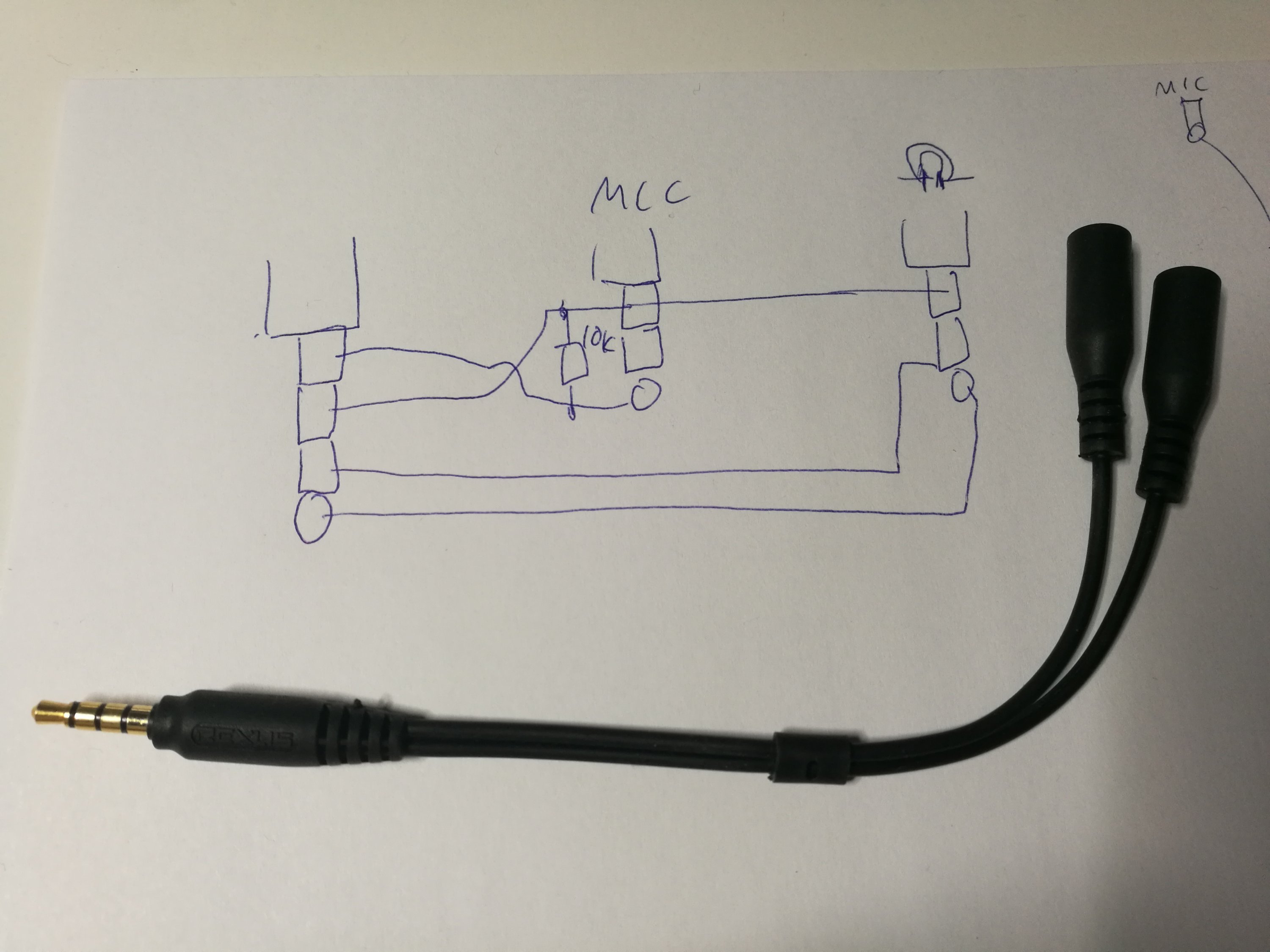
A trs plug can be used for. 3 5mm trrs jack wiring diagram a pcb layout is the resulting design from taking a schematic with specific components and determining how they will physically be laid out on a printed circuit board. Nov 10 trs jack wiring audio making a 4 pole trrs to 3 5mm stereo mic rhjebbushco. You have wired your connector according to the omtp standard with microphone on the second ring and ground on the final sleeve. 4 pole 35mm female wiring diagram you almost certainly know already that male 3 5mm 4 pole wiring diagrams has mm mm or mm trs audio plug pinout diagram for mm jack. Find your trs connector electrical wiring here for trs connector electrical wiring and you can print out.
A triple contact plug or trs plug or trs connector has three conductors known as tip l sleeve sand ring rthe tip l is screwed on to a steel pin that runs back through the hard rubber insulating sleeve to the connecting block to which the connecting screw is fastened and in order that the cord conductor may not touch the connecting block f an insulating washer g is placed under the screw. Wiring diagram also provides helpful suggestions for tasks that may need some extra equipment.
