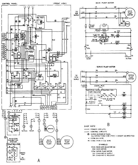
Distribution is unlimited s9086 ky stm 010ch 320r2 revision 2 title 1 at at fipgtype at at title at at fipgtype at at published by direction of commander naval sea systems. The good news is that most boatbuilders use the american boat and yacht council color codes for boat wiring.
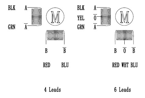
Nema 23 Stepper Motor Wiring Diagram Us Ship 3axis Nema 23
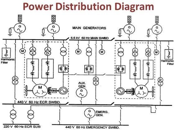
Ship wiring diagram. If youre running wiring through your boats engine room abyc standards assume the temperature is 122f 50c. This is why a good diagram is important for wiring your home accurately and according to electrical codes. Approved for public release. Onboard a merchant ship the supply is usually 440 volts 60 hertz however higher voltages of 66kv are possible on lng tankers special purpose ships and passenger vessels having electrical propulsion. Naval ships technical manual chapter 320 electric power distribution systems this chapter supersedes chapter 320 dated 30 june 1995 distribution statement a. Jun 22 2020 cutaway drawings technical illustrations and diagrams of ships from around the web.
Select from the options below to show the appropriate wiring diagram depending on your particular setup. Wiring schematics distributor kit wiring diagram j1939 to nema2000 wiring mefi 4 mefi 4 engine controls schematic 43l 57l mefi 4 ecm circuit board layout 57 60 81l mefi 4 engine controls schematic 60l mefi 4 ecm engine wiring diagram 81l 57l wiring harness schematic 472605 mefi 5 mefi 5 engine controls schematic 60l mefi 5. The main bus bar. Electrical wiring representations are made up of 2 points. The temperature where you are running your wiring affects how much current it can safely carry. Signs that represent the elements in the circuit as well as lines that represent the links in between them.
Tracing wiring runs in boats can be a painful task. The main bus bar can be found inside the main switch board. Wire is often run in concealed areas and at the ends where it is visible its usually bundled with a bunch of other wires. The boats bilge pump float switch. Keep your diagram nearby. A wiring diagram is a type of schematic which uses abstract photographic icons to reveal all the affiliations of components in a system.
Wiring diagrams can be helpful in many ways including illustrated wire colors showing where different elements of your project go using electrical symbols and showing what wire goes where. See more ideas about technical illustration ship cutaway. System wiring below is a diagram to show how to wire a typical brushless motor system. Briefly the higher the ambient temperature of the environment the lower the amount of amperage the cable can carry. This way even if your battery switch is off if your boat starts filling with water the pump will still kick on. Specific colors are used for specific equipment.
Its pretty standard in boat wiring to bypass the main battery switch for one thing.


