A diagram that represents the elements of a system using abstract graphic drawings or realistic pictures. Wiring diagrams 14 part 5 start up and operation 18 part 6 maintenance and troubleshooting 19 limited warranty 21 customer installation record form 23 note.

Wiring Diagrams 0 Wire Color Circuit Connector Wire
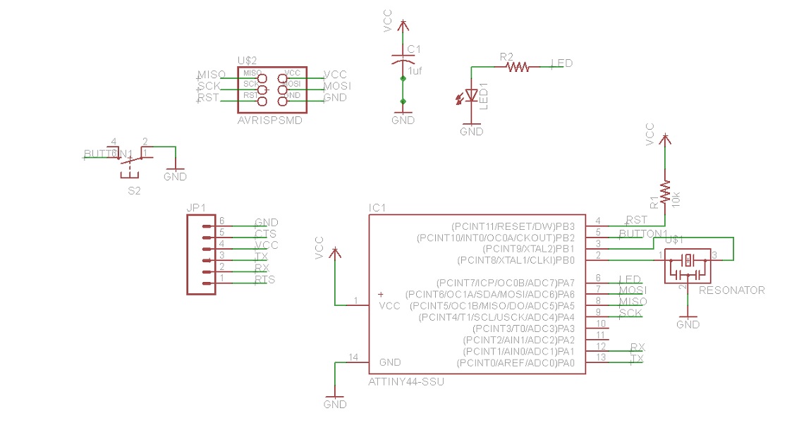
Ssu switch wiring diagram. Wiring diagrams wiring diagrams for 2 way switches 3 way switches 4 way switches outlets and more. Electrician circuit drawings and wiring diagrams youth explore trades skills 3 pictorial diagram. This pin is the input terminal to the coil inside the relay. How to wire a single switch. For now let me show you a simple wiring diagram that details how to connect a switch and accessory to a relay. Unlike a schematic its concerned with the connections between the different parts of a circuit or parts of an entire electrical system.
Ssu models this manual must only be used by a qualified installer service technician. Explanation of wiring diagram 1. Double pole switch opens both sides of circuit. Wiring a 4 way switch. Circuit electrical wiring enters the switch box. This supplies a positive signal to pin 86 of the relay.
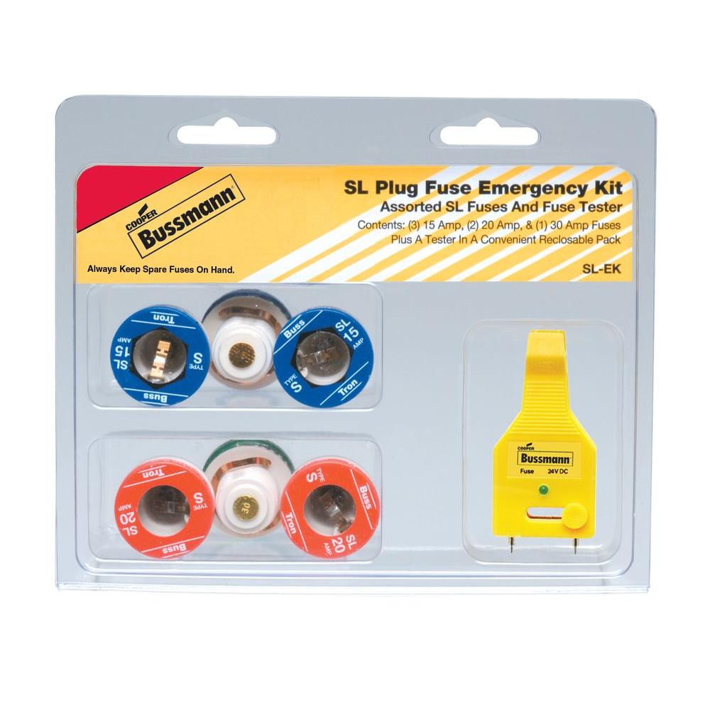
Part 4 heater control and wiring 14 a. This simple diagram below will give you a better understanding of what this circuit is accomplishing. Wiring a 2 way switch how to wire a 2 way switch how to change or replace a basic onoff 2 way switch wiring a 3 way switch how to wire a 3 way switch how to wire a 3 way switch circuit and teach you how the circuit works. Switch control1 pilot light2 max motor size hp description agency information sou 2 14 handy 1 34 fuse receptacle only no switch or outlet ul csa sru 1 12 fused outlet ul ssu 1 x 12 fused switch ul csa sow 2 34 switch 1 34 fuse receptacle only no switch or outlet ul csa srw 1 12 fused outlet ul ssw 1 x 12 fused switch ul csa. Featuring wiring diagrams for single pole wall switches commonly used in the home. Switch turns power to fused load off or on.
This circuit is served by its own circuit breaker in the breaker box properly called the main service panelthe circuit wiring runs from the service panel to the disconnect switch and from there to the furnace. A wiring diagram is the most common form of the electrical wiring diagram. According to building codes a furnace must be supplied by a dedicated circuit meaning the circuit cannot supply power to anything other than the furnace. Sty can be used for two separate 125v motors not larger than 1 2 hp with the common switch or a single motor not larger than 2 hp at 250v maximum of 150v to ground. Switch wiring shows the power source power in starts at the switch box. From this diagram you can see that we have a physical switch which will be inside our vehicle cabin.
Switch light indicates power to load dark when switch off or fuse open. When wiring a 2 way switch circuit all we want to do is to control the black wire hot wire to turn on and off the load. Black wire power or hot wire white wire neutral bare copper ground. A diagram that uses lines to represent the wires and symbols to represent components. Obey all local codes.
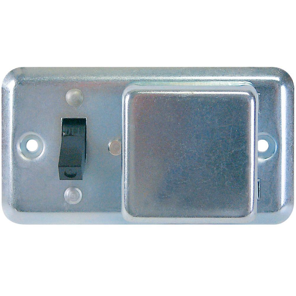
Gallery of Ssu Switch Wiring Diagram