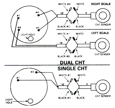
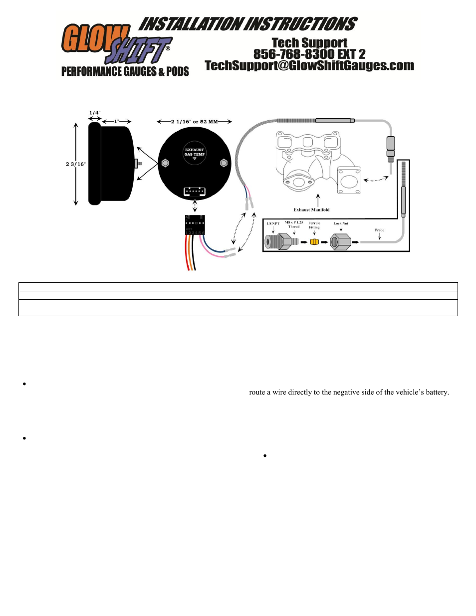
Do not cut the 48 inch egt probe leads. Single cht egt instruments.

Ec7e 2002 Chrysler Sebring Wiring Diagram Digital Resources
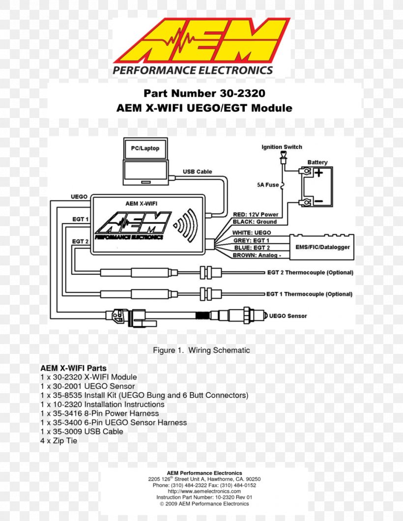
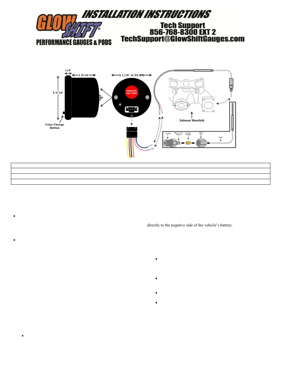
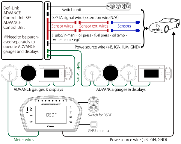
Egt gauge wiring diagram. Old style k29 k29p k29px instrument. Always disconnect battery ground before making any electrical connections. No this gauge is unlit. The red wire is the 12v power lead which is wired to the fused onoff switch on the instrument panel. High pressure oil pressure hpop gauge wiring harness. View in catalog view in catalog.
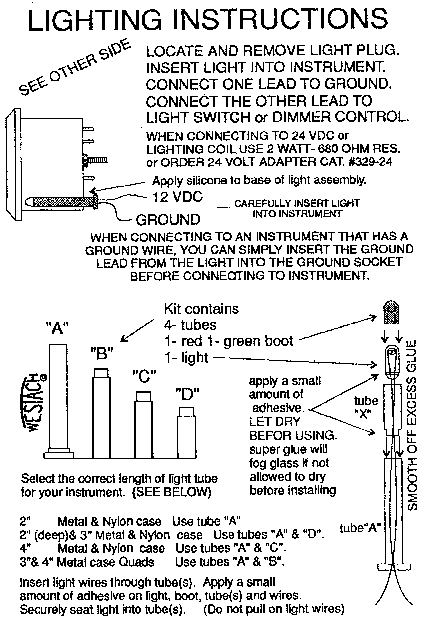
Each set of instructions is accompanied by a series of diagrams visually explaining the instructions for your convenience. Fuel rail pressure gauge wiring harness. Westach general information instrument wiring instructions. They will open in a new window so make sure you turn your popup blocker off. Do not deviate from assembly or wiring instructions. The yellow wire is the capacitance gauge signal wire which is wired to the fuel gauge on the instrument panel.
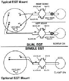
Proper polarity is required and good continuity is a must. Instead itll be a direct wire from pin 50 straight to the pas pressure switch. Instructions are in blue and if you just want the diagrams they are in red. The connection e17 on the diagram wont exist if the loom isnt egt equipped already. 7 color gauge series extended sensor wiring harness. Please note on the dual gauge diagram above 4 and 5 are on one side of the gauge while 1 and 8 are on the other.
7 color gauge series wiring kit. The black wire from the capacitance gauge is wired to ground. Add on clock power harness for 2002 2005 subaru impreza wrx. So if you havnt got the connection itll be simple enough to pick it up. 1 800 265 1818 do not cut sender wire. 2a1 instrument 2a2 instrument 2c1 instrument 2c2 instrument.
Here are instructions for falcon gauge instruments. The falcon 2 inch round dual egt gauge comes with the gauge wiring and instructions only. Is the gauge lit for night use. Westach designs and builds quality gauges and instruments for a wide range of applications including personal aircraft standard diesel electric and hybrid automotive vehicles and agriculture. 28 wiring diagram 281 typical residential split phase installation figure 4 is a schematic wiring diagram showing a typical split phase installation where egauge is used to measure the amount of power being supplied by the power utility cts 12 and the power supplied by a single phase solar inverter ct 3. 3a1 instrument 3a2 instrument 3c1 instrument 3c2 instrument.
