Wellborn assortment of jet pump pressure switch wiring diagram. December 19 2018 by larry a.

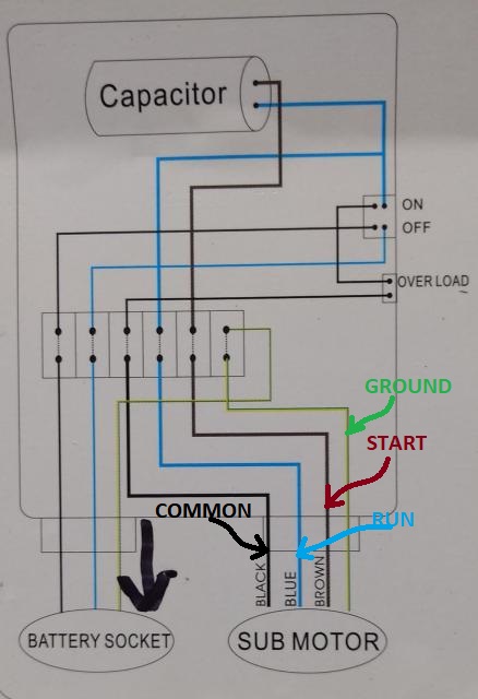
Water Pump Wiring Troubleshooting Amp Repair Pump Wiring Diagrams
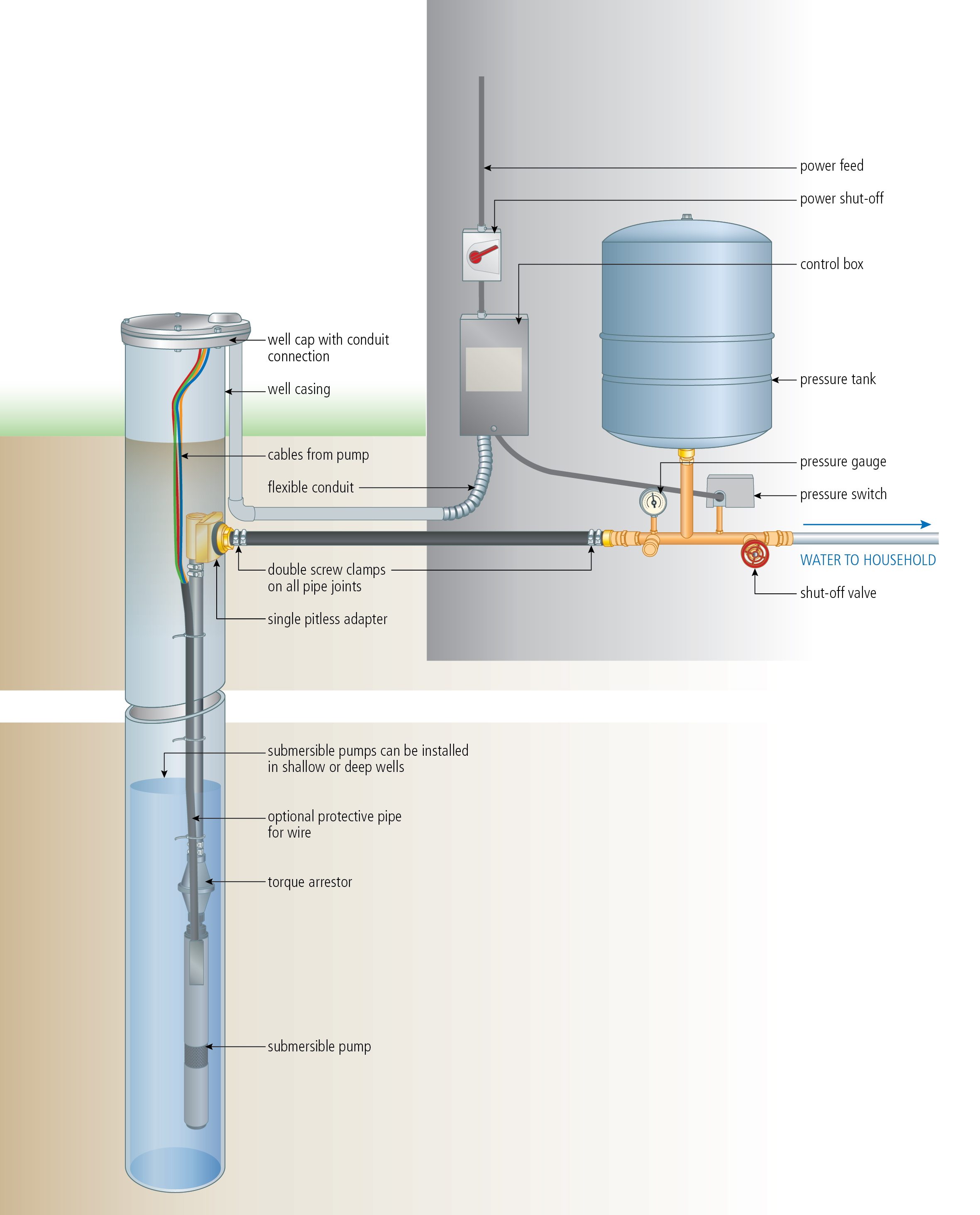
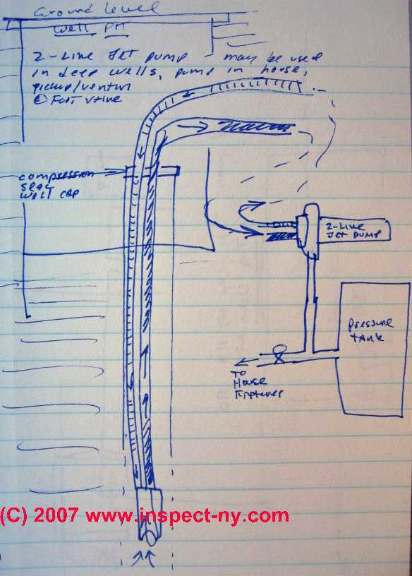
Jet pump wiring diagram. A wiring diagram is a streamlined standard pictorial depiction of an electrical circuit. For wells deeper than 80 a submersible pump system is recommended. Check motor wiring diagram. If replacing the switch we recommend using one with a 30 5 psi setting. Reconnect for proper voltage as per wiring diagram. Deep well jet systems are used when the water depth is between 20 and 80.
The basic 3 way switch wiring diagram this entry was posted in outdoor wiring diagrams and tagged 2 speed pump 230 volt pump breaker disconnect how to wire a pump pump wiring wiring diagram. Check air temperature where pump is located. It reveals the components of the circuit as simplified shapes and the power and signal links between the devices. Jet pumps usually come with a 30 50 pressure switch factory installed on the pump. Apply soapy water to entire surface above water line. We recommend a captive air pump tank.
Continuous operation at very low pressure places heavy overload on pump. If over 100 degrees f overload may be tripped out on external head. We recommend that a licensed contractor install all new systems and replace existing pumps and motors. Technically qualified personnel should install pumps and motors. Continuous operation at very low pressure places heavy overload on pump. This can cause overload protection to trip.
Install globe valve on discharge line and throttle to increase pressure. Failure to install in compliance with local and national codes and manufacturers recommendations may result in electrical shock fire hazard unsatisfactory performance and. This can cause overload protection to trip. Check motor wiring diagram.


