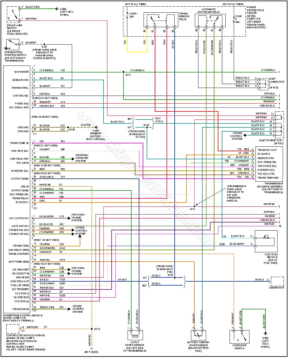
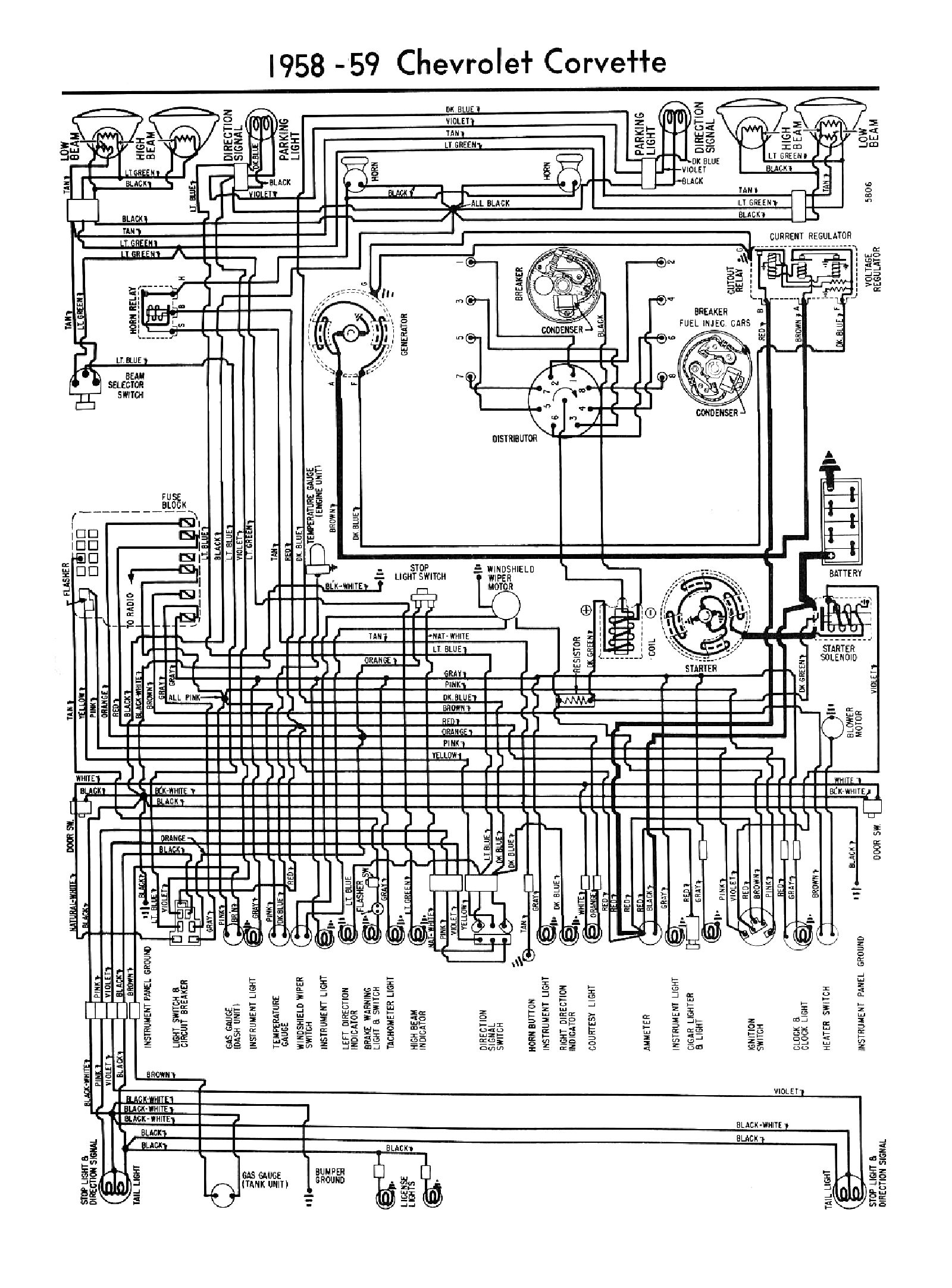
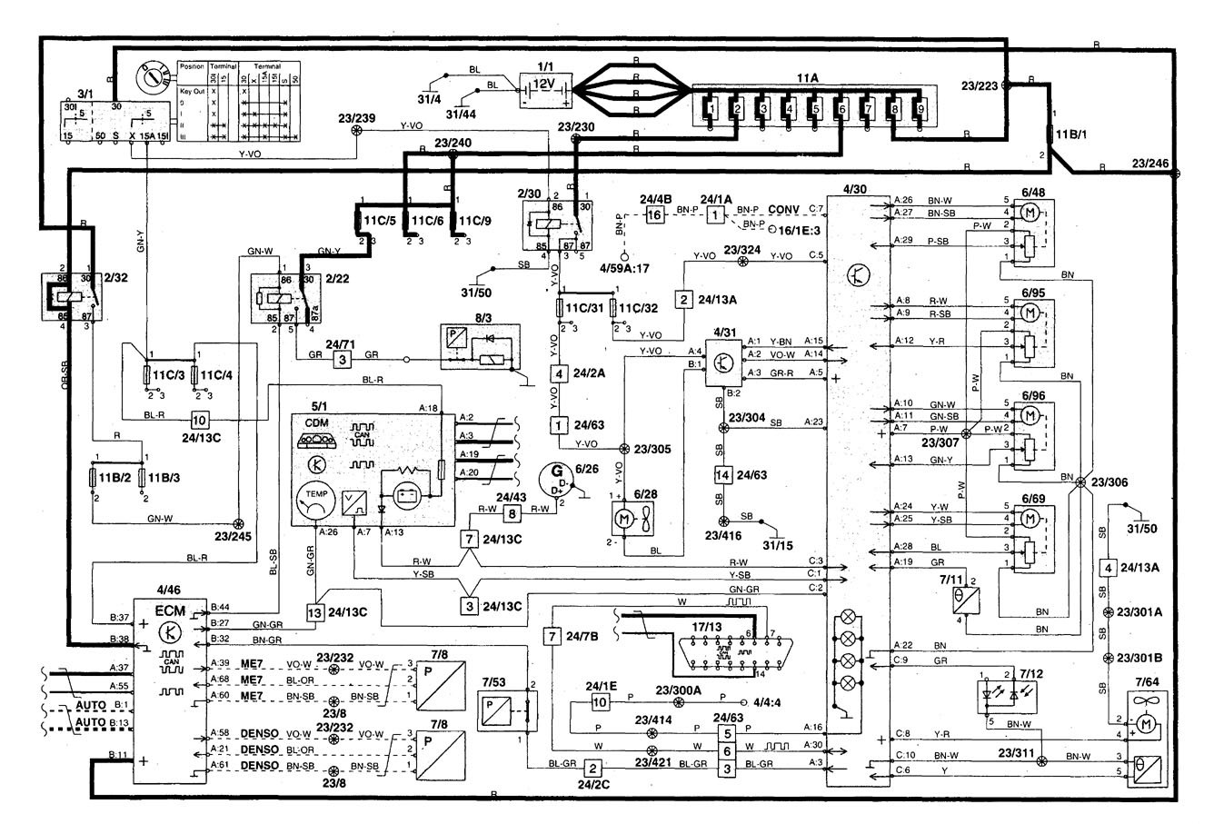
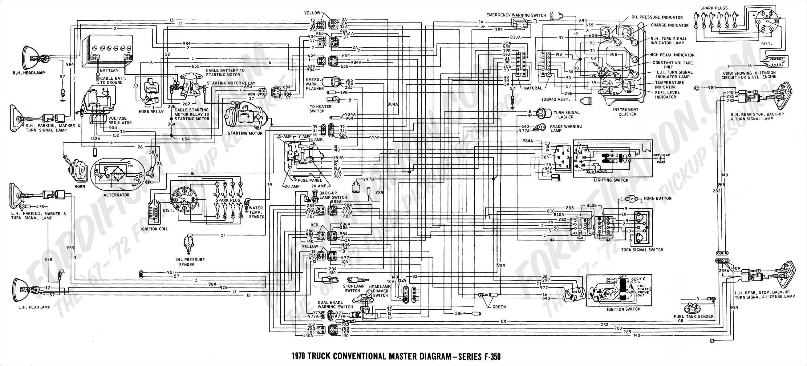
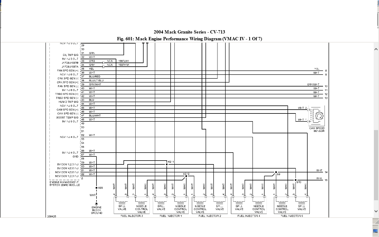
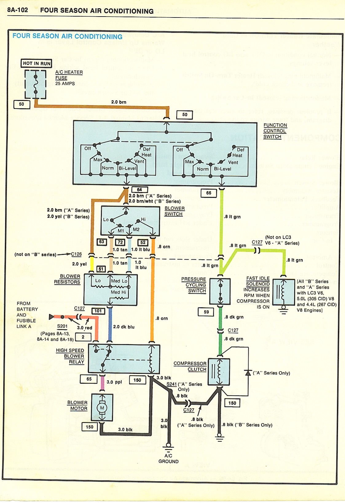
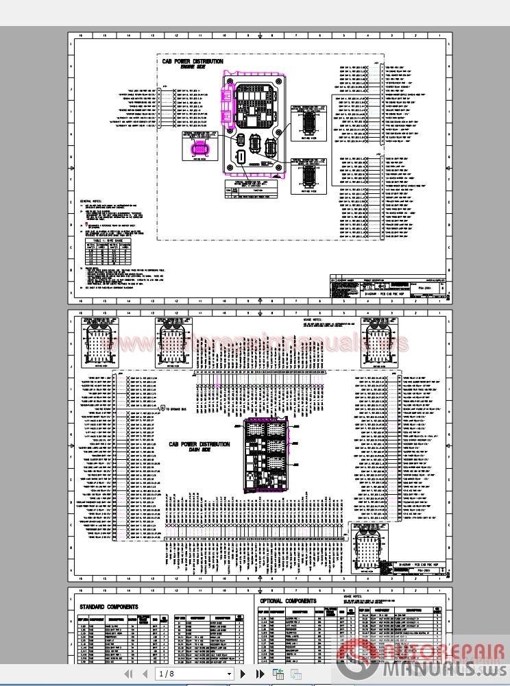
Carriertempthermostat the carrier tempsys tem is a control system which includes a relay pack temp system thermostat sensors and appropriate wiringthe temp thermostat is the system controller and works much. The first and most common is the ladder diagram so called because it looks like the symbols that are used to represent the components in the system have been placed on the rungs of a ladder.

Chevrolet Colorado Engine 2 8 Wiring Diagram Manual 2016
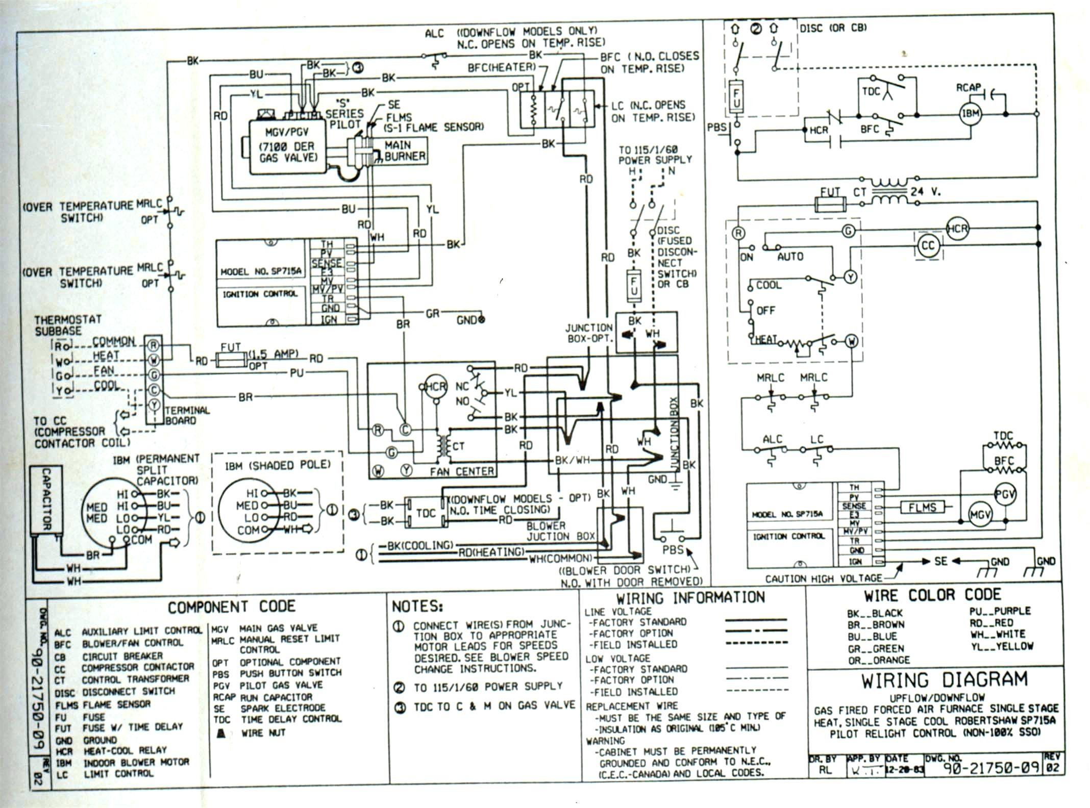
Hvac wiring diagram pdf. 5 expanded table 340085 101 340085 101 340086 101 340086 101 340086 101 342878 101. A wiring diagram is a streamlined conventional pictorial representation of an electrical circuit. Types of wiring diagrams there are three basic types of wiring diagrams used in the hvacr industrytoday. On a call for heating the thermostat activates the water or steam control valve or electric heater to meet heating requirements. It reveals the components of the circuit as streamlined shapes and the power as well as signal connections between the gadgets. Hvac wiring diagram pdf sample variety of hvac wiring diagram pdf.
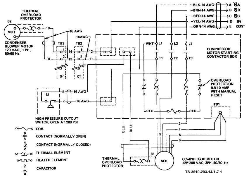
Always refer to your thermostat or equipment installation guides to verify proper wiring. From this point forward ladder dia. Air conditioning unit wiring diagrams fig. Wiring diagram manual split system air conditioner 421 03 5400 01 specifications subject to change without notice. Note some ac systems will have a blue wire with a pink stripe in place of the yellow or y wire. Air conditioning ac contactor control board 1 this diagram is to be used as reference for the low voltage control wiring of your heating and ac system.
138ck018 32 34 38ckm024 32 34 38ckm030 30 32 38ckm036 and 042 33 34 38ckm048 35 36 208 230v 1 phase 60 hertz a93410 23 5 red or blk red or blk 208230 power supply 10 equip gnd l1 l2 11 21 23 blk blu blu yel yel brn blu blk yel yel h c f ofm brn blk vio blu blk blu blk.

