Switch 1 piece 5. Batten holder 1 piece 6.

Short Circuit Test Wikipedia
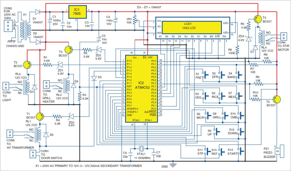
Series testing board wiring diagram. Each light bulb have their own requirement of pressure v and their own. You can test any electric elements with this. 100 watt bulb 1 piece 7. To wired the electric testing board first of all connect the neutral wire to lamp holder and then connect the phase wire to outlet terminal and then connect a wire between socket outlet and holder as shown in below diagram. Electrical series testing board. So i think it is very useful post for electric students.
Series testing board wiring diagram if you like this video please like comment and share with your friends. Wiring lights in series connection diagram current and voltage in series circuit. Dont forget to subscribe. A series test lamp is a way that electricians would test or find a short circuit somewhere in a residential building. Tools and elements you need to make electrical series testing board. After t hat connect a wire between outlet 2nd terminal and bulb socket 2nd terminal same connect an electric wire between the switch 2nd terminal and the light bulb socketholder 2nd terminal where we connected an electric wire between socket and holder.
How to make an electrical series testing board what is series lamp test. How to wire a series electric testing board to wire a simple testing board you will require a electrical outlet or 2 pin socket a incandescent light bulb and holder. Dont forget to subscribe. Series board wiring diagram in this video im show youseries board wiring diagram. First i want to show how to wire lights in series connection in simple words a series circuit is a circuit in which we have only one path for current flow and only one way to flow the electron. Series parallel testing board circuit diagram hindi part 2 wiring connection with drawing.
To make or wire the complete series board fist of all connect the phase line wire to the socket outlet terminals and then connect the one way switch. Two pin socket 2 piece 3. When we talking about the ac or dc light bulbs we know that we have to terminals in a bulbs or to contacts to provide the electric supply. Some people called it electric testing board. 64 plastic board 1 piece 2. Fuse 1 piece 4.
Series testing board but my last diagram about series board which is only for connectivity testing shortage testing or compressor terminals testing but in this post you will learn that how can you make a testing board from which you can test the low resistance electrical appliances such as electric heater iron etc. If you like this video like comment and share with your friends.


/GettyImages-155903363-5b2819f6119fa800366f917f.jpg)


