0140ct9201 pdf 21 mb 21 mb. Schneider contactor wiring diagram elegant how to wire a subpanel building wiring representations reveal the approximate places and also interconnections of receptacles lights and long term electrical services in a structure.

How To Connect The Watchmon4 To The Schneider Electric
Schneider contactor wiring diagram. Adjoining cable paths may be shown about where particular receptacles or fixtures need to get on a common circuit. This book contains examples of control circuits motor starting switches and wiring diagrams for ac manual starters drum switches starters contactors relays limit switches and lighting contactors. Assortment of schneider electric contactor wiring diagram. It reveals the components of the circuit as streamlined shapes as well as the power as well as signal links in between the devices. November 25 2018 by larry a. Overload relays ac motors dc motors wiring capacitors resistors semiconductors table 1 standard elementary diagram symbols contd.
A wiring diagram is a streamlined conventional pictorial depiction of an electrical circuit. Definite purpose contactors are ideal for heating air conditioning refrigeration data processing and food service equipment. Wiring diagram book a1 15 b1 b2 16 18 b3 a2 b1 b3 15 supply voltage 16 18 l m h 2 levels b2 l1 f u 1 460 v f u 2 l2 l3 gnd h1 h3 h2 h4 f u 3 x1a f u 4 f u 5 x2a r power on optional x1 x2115 v. Schneider electric contactor wiring diagram schneider electric contactor wiring diagram lovely charming wiring d diagram square contactor 8536s. Schneider electric contactor wiring diagram exactly whats wiring diagram. Features quick connect terminals and binder head screws allow for easy wiring.
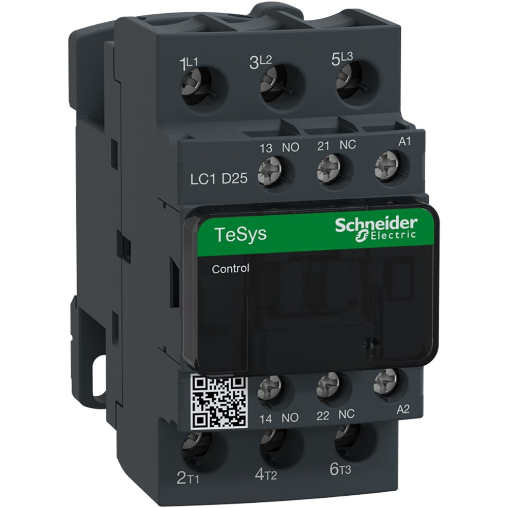
These diagrams do not relate to such systems unless the 2 right hand pins are first removed. It shows the elements of the circuit as simplified shapes and also the power as well as signal connections between the devices. A wiring diagram is a streamlined conventional pictorial depiction of an electric circuit. Assortment of schneider lc1d25 wiring diagram. The tesys k range contactors lc1k and tesys lr overloads lr2k have additional pins on their overloads to make direct connection to terminals 14 on contactor to 95 on overload and a2 on contactor to 96 on overload. A wiring diagram is a type of schematic which uses abstract pictorial signs to reveal all the interconnections of components in a system.
July 8 2018 by larry a. Wiring diagram for telemecanique lc1 contactor replacements by us breaker lr aux nc1d aux nc1d aux m control supply voltage is the same as the main circuit voltage 3 phase control supply voltage is not the same as the main circuit voltage 3 phase connect to other supply control supply voltage is the same. Compact 1 and 2 pole contactors are available as well as full s ize devices with 2 3 or 4 poles.


