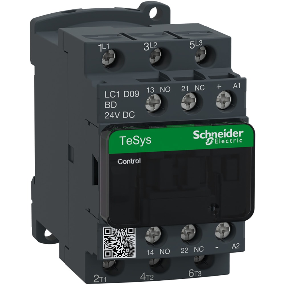
Type s contactors are designed for operation at 600 volts ac 50 60 hertz. Features quick connect terminals and binder head screws allow for easy wiring.

Schneider Electric Wiring Diagram Pdf Diagram Pdf
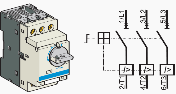
Schneider contactor wiring diagram pdf. Power block diagram 1l1 a2 2t1 3l2 b2 4t2 5l3 c2 6t3 ac line supply 2t1 4t2 6t3 motor. References tesys lrd overload relays thermal overload relays for tesys d contactors class 10 a characteristics. 3 lrd3803 available end 2017. A wiring diagram is a streamlined conventional photographic representation of an electric circuit. Sizes 3 7 contactors use a class 9999. Compact 1 and 2 pole contactors are available as well as full s ize devices with 2 3 or 4 poles.
Lc1d09p7 tesys d contactor 3p3 no ac 3 440 v 9 a 230 v ac coil. Box lugs are standard on contactors 40 a and larger. Assortment of schneider electric contactor wiring diagram. Refer to figure 1 and to the wiring diagrams in appendix a beginning on page 79. Collection of contactor wiring diagram pdf. Iec contactors 41 42 iec contactors and auxiliary contact blocks 41 input modules and reversing contactors 42 type s ac magnetic starters43 50 class 8536 43 50 8538 and 8539 4549 1 phase size 00 to 3 43 2 phase and 3 phase size 00 to 5 44.
If a shortingbypass contactor is used connect it between l1 l2 and l3 on the line side supply terminals and a2 b2 and c2 of the ats48 soft starter. Ls contactor wiring diagram inspirationa schneider electric wiring diagram for schneider contactor refrence 2 lights 2 switches wiring diagram excel archives noodesign inspirationa wiring. Sizes 00 2 contactors use a class 9999 sx11 auxiliary contact as the holding circuit contact. This instruction bulletin contains ratings start up procedures programming information troubleshooting procedures and wiring diagrams for the motorpact soft start. Click on the image to enlarge and then save it to your computer by right clicking on the image. This book contains examples of control circuits motor starting switches and wiring diagrams for ac manual starters drum switches starters contactors relays limit switches and lighting contactors.
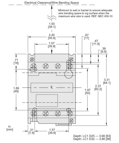
0140ct9201 pdf 21 mb 21 mb. Pages b1132 to b1134 dimensions. An exclusive din track mounting option may reduce installation costs. It shows the components of the circuit as streamlined shapes and the power and signal connections in between the tools. Holding circuit contact a normally open holding circuit contact for three wire control is provided on all contactors as standard. In accordance with local electrical wiring regulations a size 4 insulated allen key must be used reference ladallen4 see page b829.
Pages b1135 to b1137.
