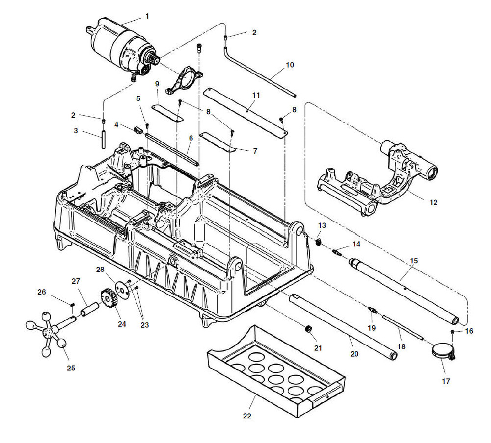
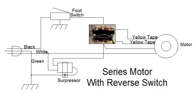
It shows the components of the circuit as simplified shapes and the power and signal friends together with the devices. Description 1 94337 screw button head 1 4 20 x 3 8 7 2 94082 rear cover.

Download 99 Ford F 150 Fuse Box Wiring Diagram
Ridgid 535 wiring diagram. Do not order by reference number. 2 535a pipe and bolt threading machine drive shaft assembly 2 1 3 5 7 16 12 18 22 27 26 25 23 15 14 10 9 8 4 6 12 13 17 16 15 11 20 19 19 21 24 4 28 31 1 13 29 30 ref. Pipe and bolt threading machine 535 manual 1101 2301 26 28 25 25 27 30 29 34 33 16 15 24 32 31 12 8 11 8 8 8 4 3 9 7 8 5 2 1 6 10 20 17 16 23 21 22 13. 17 2nd intermediate ref. 16 1st intermediate ref. The ridgid model 535 threading machine is an elec tric motor driven machine which centers and chucks pipe conduit and rod bolt stock and rotates it while threading cutting and reaming operations are per formed.
Left hand or right hand rotation can be selected with the foroffrev switch. Ridgid 535 wiring diagram wiring diagram is a simplified normal pictorial representation of an electrical circuit. Refer to page 21 for wiring diagram. Order parts by catalog number only. 535 ridge tool companyelyria ohio usa. 400a 535 802 motor no.
3 ridge tool companyelyria ohio usa. Catalog description description 94332 screw button head 20 x 4 44930 stop screw. Page 1 535 manual pipe and bolt threading machine main components note. 54 pipe and bolt threading machine speed change gear chart machine model no.


