The marine sae j1171 testing procedure is as follows. A sparking device similar to a spark plug is installed in the brush area of the alternator.

Installing A Automatic Charging Relay Acr Practical Boat
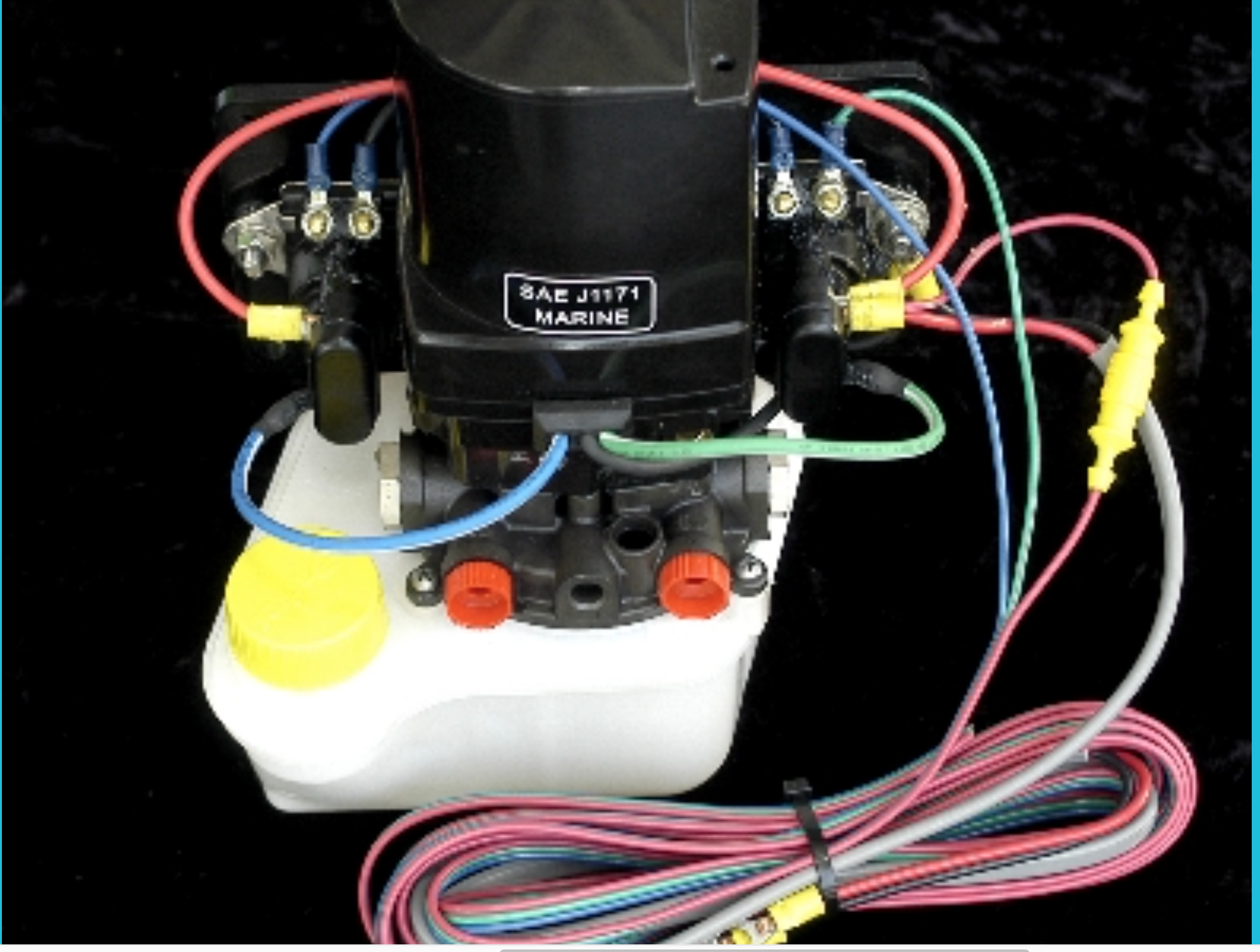
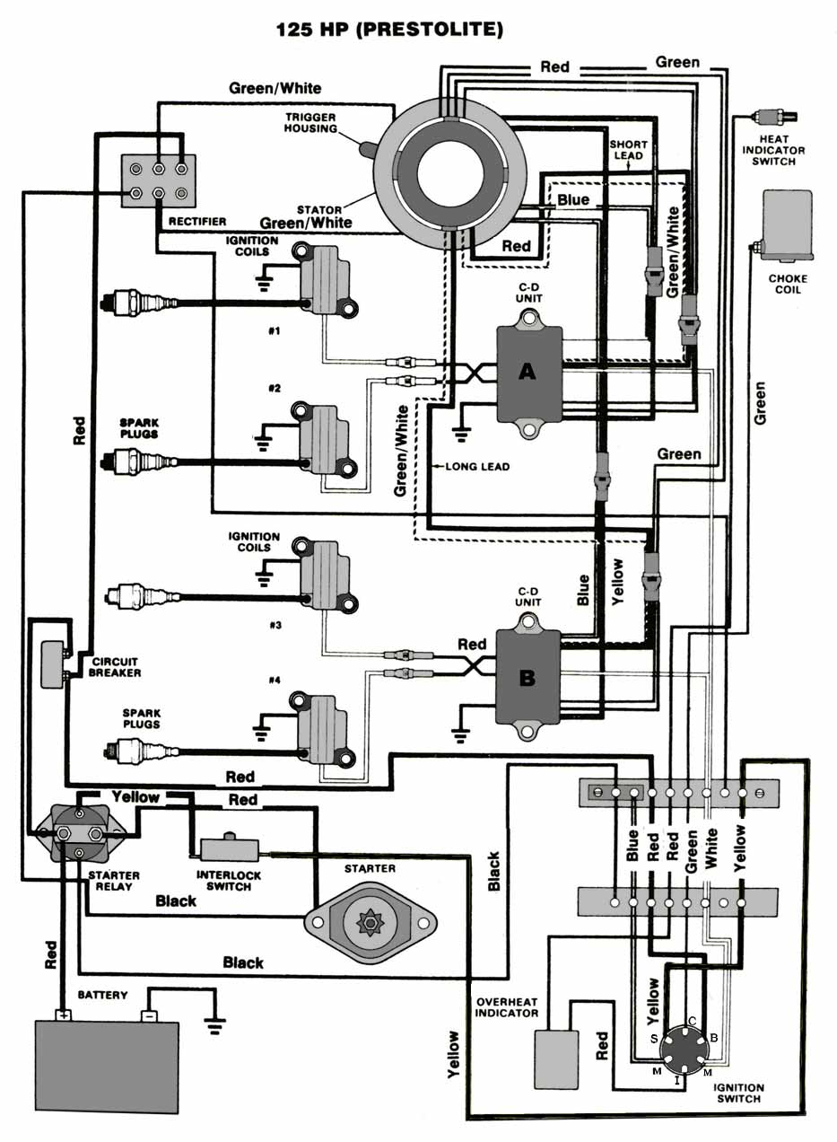
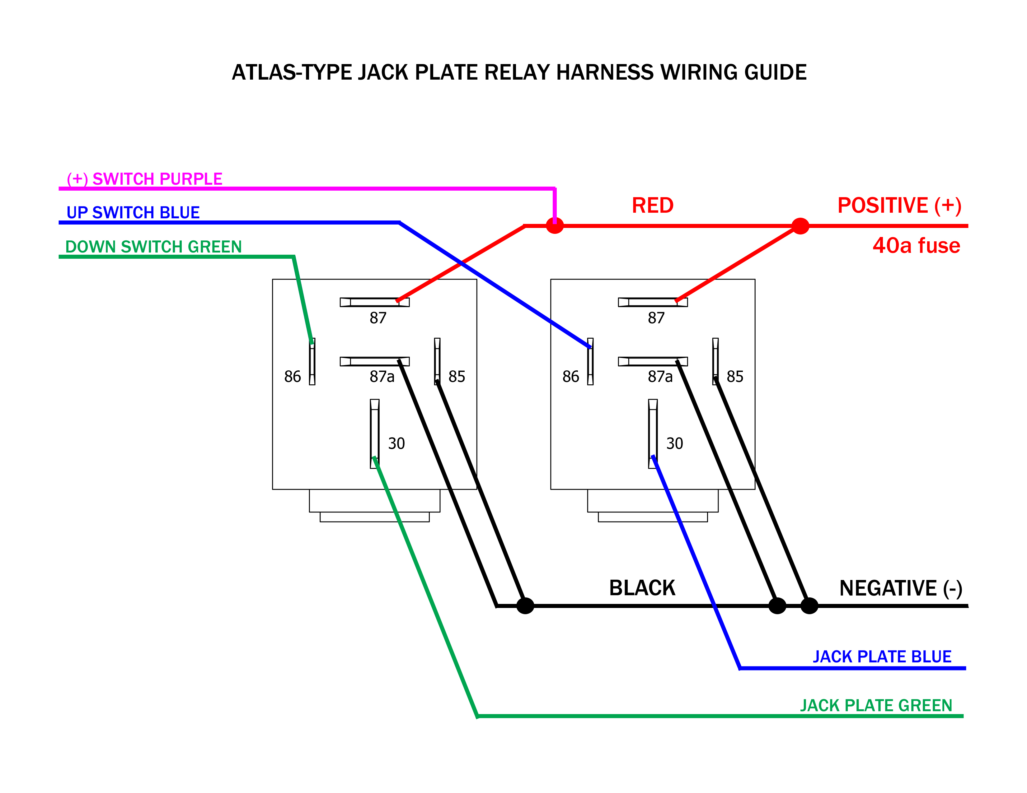
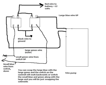
Sae j1171 wiring diagram. Another device is also installed in the brush area of the alternator to supply a specified mixture of pr opane gas and oxygen. Some models may also be equipped with a trim indicator sender. A sparking device similar to a spark plug is installed in the brush area of the alternator. With our online resources you can. The hydraulic sub system contains a prestolite or oildyne hydraulic pump the trim cylinders a reverse lock valve and the necessary hoses and fittings. Ul 1500 and sae j1171 external ignition protection requirements rated ip67 temporary immersion for 30 minutes wire size and fuse rating chart awg charging amps minimum wire size fuse rating.
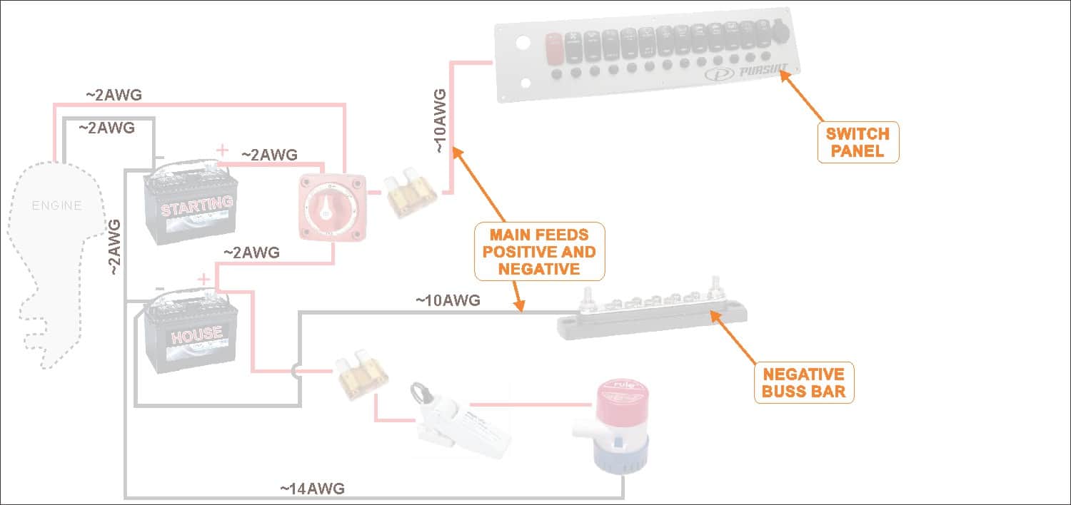
You will be glad to know that right now sae j1171 marine trim pump service manual pdf is available on our online library. Electrical sub system single or dual solenoids may be used. The wiring diagram illustrated on the back page represents a common installation and is not meant to be a guide for wiring a specific vessel. Sae j1171 marine trim pump service manual pdf are you looking for ebook sae j1171 marine trim pump service manual pdf. The alternator is then placed in an explosion proof test chamber. The alternator is then placed in an explosion proof test chamber.
Another device is also installed in the brush area of the alternator to supply a specified mixture of propane gas and oxygen. The marine sae j1171 testing procedure is as follows. Test standards to determine ignition protection include sae j1171 external ignition protection of marine electrical devices and ul 1500 ignition protection test for marine products and the electrical system requirements for boats in title 33 cfr 183410a. Figure 1 shows a typical system.
