Each wire set contains two insulated and one bare wire. Im trying to replace a single pole light switch with a timer light switch in a box that also has another single pole switch going to another light.
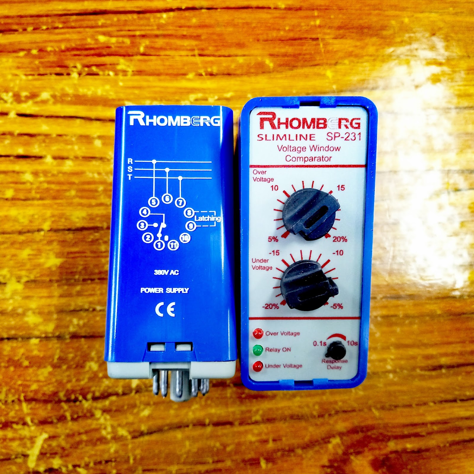
興昌電機 Hing Cheong Electric Undervoltage Overvoltage
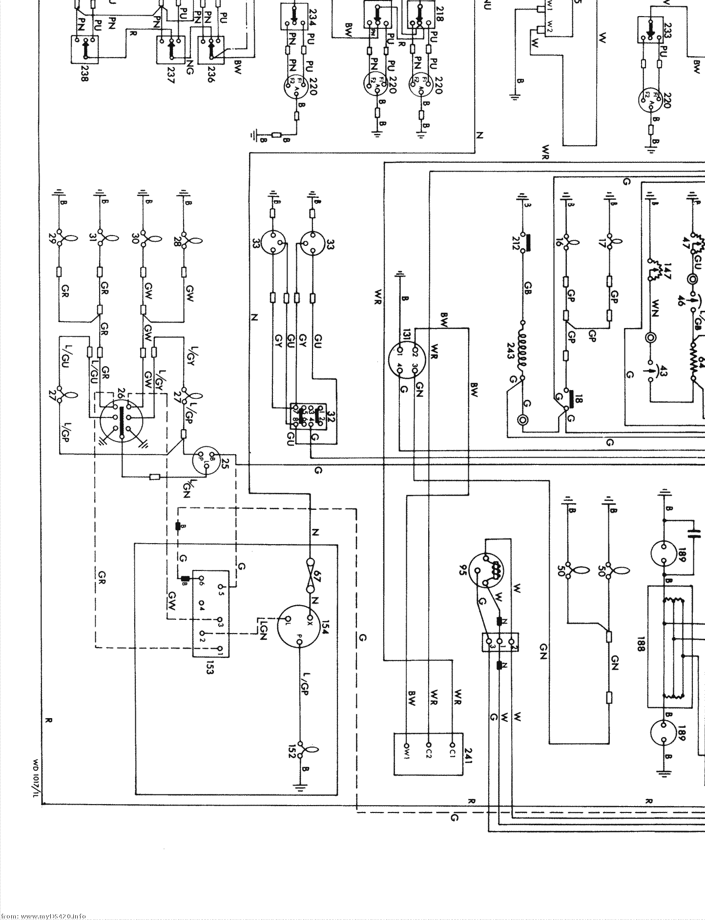
Rhomberg digital timer wiring diagram. 1600 on 1800 off release clock button. Do the same for white wires and also for the green wires. We are professional any electric timer relay timer switch time delay digital timer programmable timer switch ic timers 7day t. Two wire sets enter the timer. Im using the top tronic timer made for geysershwc up to 20amps. Intermatic prints the labels above each terminal.
At first time the timer is in 24h mode. First time use this timer device please input ac and let battery recharge. First time use this timer swich please input ac and let battery recharge after then press reset key. 2100 on 2300 off or recommended power utilities times 2100 on 0600 off programming timer wiring push p button once program 1 on appears connect 220v to live l terminal and neutral n terminal on timer. This video will show you how to connect a timer to your geyserhot water cylinder. An example of single pole and three way wiring follow.
Strip the existing wire ends 716 to 716. If you want 24h mode press on clock key for 5 seconds to return. At first time the timer swich is in 24h mode if you you want change to 12h mode please press on key 5 sce and lcd will display am if you want rechang to 24h mode and press on key 5 sce to return. After that press reset key. Time and date set. Use the wire connectors to connect the black timer switch wire to the black wall box wire.
The timer uses a gr label to identify its green colored ground screw. The timer keeps zeroing out to the flashing initial setup screen after about 5 or 6 toggles of the other light switch in the box. If the wall box features a non insulated ground that is ok just connect that to the green switch wire or secure it around the ground screw on the switch if it does not include a green wire tail. Home automation and light switch wiring electrical question. Wire the timer into the wall box. Step 5 identify each wire terminal using the numbered labels 1 through 4 for line and load terminal identification.
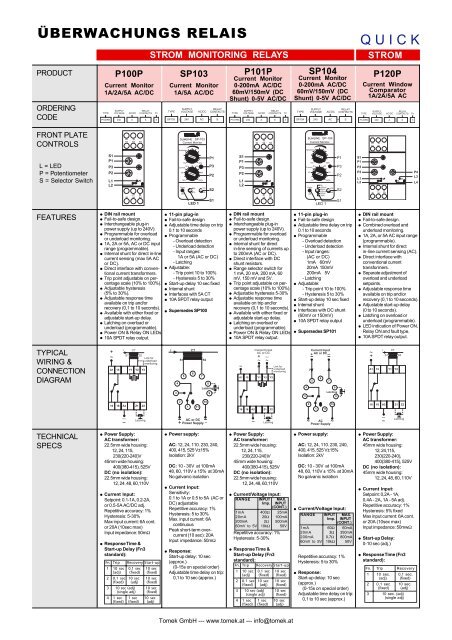
Multi function timers typical wiring connection diagram features ordering code front plate controls technical specs product at100 multi function timer st100st101 multi function timer at110 electronic reset timer 48t101 delayed on interval one shot timer 48t100 multi function timer l led p potentiometer s selector switch. If you you want to change to 12h mode please press on clock key for 5 seconds and lcd will display am. Single pole wiring 120 v line wire a wire d wire b wire c neutral load timer a black connects to the hot black wire from the power source.

