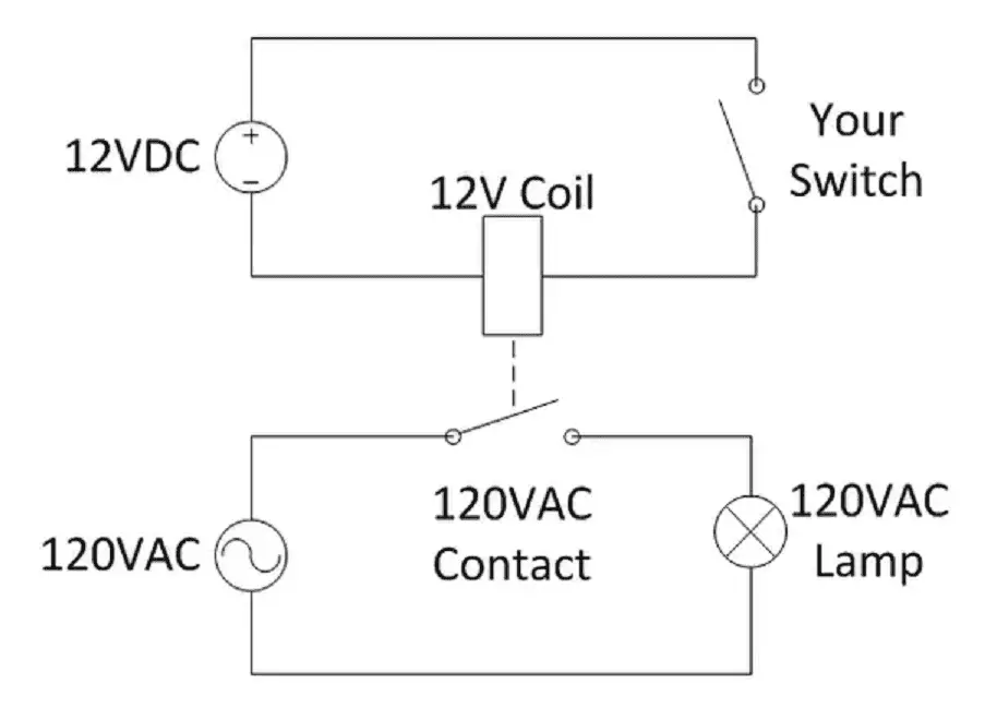
41 elevator shunt simplified air products controls space age mr 204 c multi voltage control relay dpdt space age electronics inc mr 100 series multi volt motorcycle wiring diagram kawasaki. Wiring load power source load n ac ac n caution.

Download Diagram Pioneer Wiring Deh X1900ub
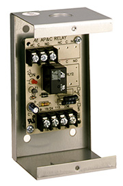
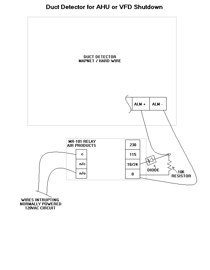
Mr101 relay wiring diagram. 25hp 125250vac nc 33 hp 125250vac no relay energized led input. Installation wiring typical for one module position mr101 mr104 mr201 mr204 specifications ordering information model description mr101t single spdt relay with led and track mounting hardware mr101c single spdt relay with led mounted in metal enclosure mr104t four position spdt relay with leds and track mounting hardware. Mr101 relay wiring diagram. Relays may be snapped apart from a standard four module assembly and used independently. 7a at 30vdc 10a at 125vac 7a at 250vac inductive. They relay contains a red led mr100 200 series which indicates the relay coil is energized.
Each relay contains a red light emitting diode led which indicates the relay coil is energized. Tension tous puissance avant linstallation ou service nc c no on mr 101 spdt contact resistive. Multi voltage control relays product description the mr series multivoltage control relays offer spdt or dpdt 10 amp resistive contacts which may be operated by one of four input control voltages. A single relay may be energized from a voltage source of 24vdc 24vac 120vac or 230vac by wiring to appropriate input terminals. De energize all power before installation or service. A single relay may be energized from a voltage source of 24v dc 24v ac 115v ac or 230v ac depending on model number by wiring to appropriate input terminals.
A single relay may be energized from a voltage source of 24 vdc 24 vac 115 vac or 230 vac by wiring to appropriate input terminals.

