Anchored by lgs industry leading multi v vrf series lg offers complete end to end solutions that are perfectly suited for a number of commercial applications. This web site is furnished by lg electronics usa inc lg and use of the images on this lg web site is subject to the following terms and conditions.

Lats Cad 2 0 Autocad Autodesk App Store
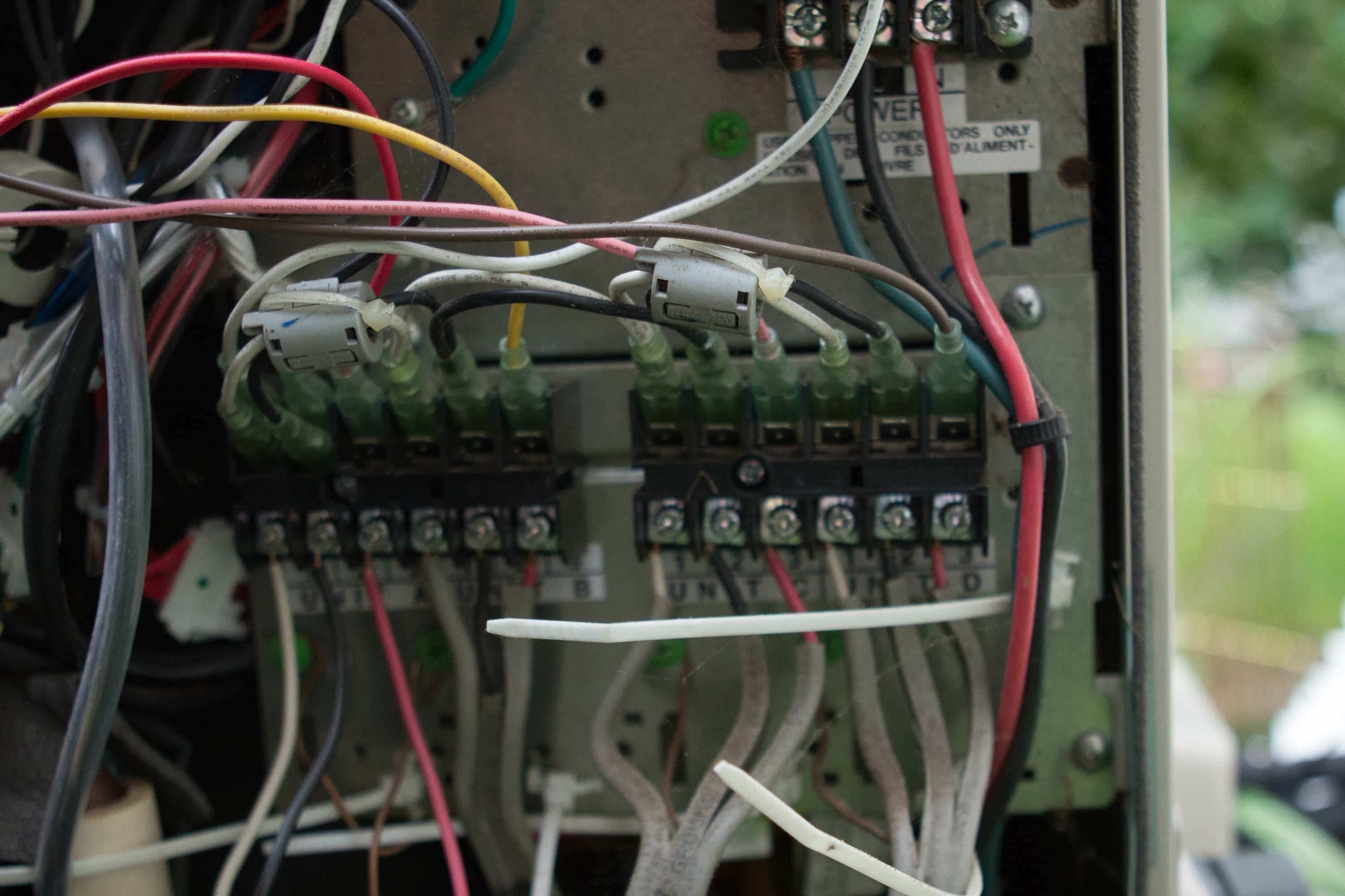
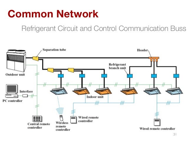
Lg vrf wiring diagram. Due to our policy of continuous product innovation some specifications may change without notification. Lg vrf solutions offer cost effectiveness and easier installation and are among the most versatile and powerful system air conditioners. This vrf system control wiring is for a vrf vrv heat recovery system with single port branch selector boxes. Headers have to have homeruns to indoor units without other y branches or headers in between. If required use inverted trap within vrf manufactures guidelines. Always create a wiring diagram that contains the exact sequence in which all the indoor units and heat recovery units are wired in relation to the outdoor unit.
All lg logos trademarks marks trade names brands and product images image or images displayed and downloaded from this lg web site must strictly comply with all. This control wiring layout is similar amongst the other vrf manufactures. The control wiring is very simple its basically two 18 gauge wires that go from the thermostat to the fan coils wire 1 so that each zone will have a wire from the thermostat to the fan coilone controller thermostat can control more than one indoor. Emmultivivoutdoorunits0416 commercial air conditioning division supersedes. Vrf system control wiring. Vrf vrv simple control wiring for a heat recovery system using single port branch selector boxes.
From the unique benefits of the multi v 5 that reduce system down time to the seamless integration of the lg multisite controls platform explore the innovative features of. Lg electronics usa inc. Due to our. Lg allows a 10 degree rotation from the horizontal plane daikin allows up to 30 degrees. The review of basic installation and configuration information should provide helpful tips to make. Lg is 20 508mm avoid creating oil traps.
Confirm minimum distances between fittings. Following the installation if any changes or variations to the design are necessary a new lats file must be. Page 57 always refer to the circuit diagram on the inside of the outdoor unit control cover. And piping diagrams in dxf format for use on cad building design drawings to ensure that the refrigerant piping design meets lgs quality standards a lats refrigerant piping design must be provided with every multi v order.

