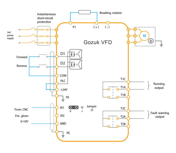
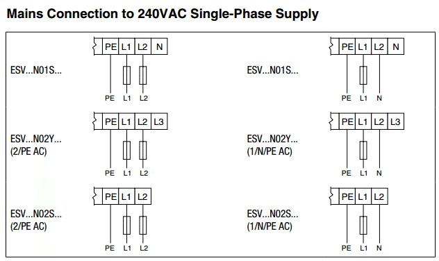
Check whether dynamic braking resistance brake chopper and dc link choke are provided only if shown in the wiring diagram. Installation operation and maintenance manual.

Electrical Safety Ground Faults Might Be Lurking In Your
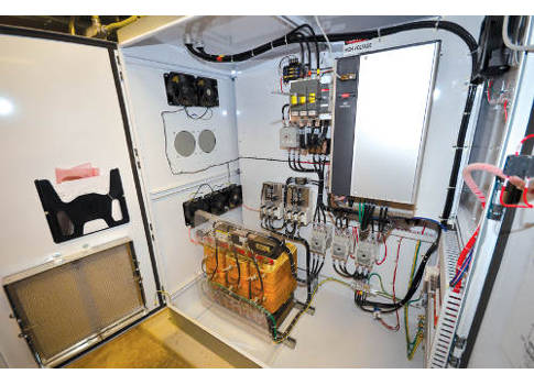
Vfd harmonic filter wiring diagram. A step by step demonstration for installing an output filter on a vfd system including best practices for a smooth operation. Passive filters are best used as individual filters for each small 6 pulse vfd or as common filters connected to a motor control center mcc supplying several vfds. 422 wiring 29 423 overtemperature protection 29 4231 programming of digital inputs for overtemperature protection 29 5 selection of advanced harmonic filter 30 51 selecting the correct ahf 30 511 how to calculate the correct filter size 30 512 calculation example 30 513 voltage boost 30 52 selection tables 31 521 terminology. The maximum temperature of the air around the hg7 filter capacitors and protection monitor should not exceed 50c 122f. Tci llc w132 n10611 grant drive germantown wisconsin 53022. Check whether the input and output line chokes harmonic filter are provided only if shown in the wiring diagram.
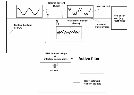
Active harmonic filter. Check whether suitable circuit breaker semiconductor fuse protection is provided for the vfd. Passive harmonic filters provide an inexpensive way to mitigate the harmonics created by vfds and other harmonic sources. Power wiring when selecting a mounting location for the hg7 filter plan for the routing of the power wiring. Open panel units list the watts of heat loss that is dissipated by the hg7 harmonic filter.
