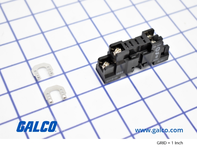
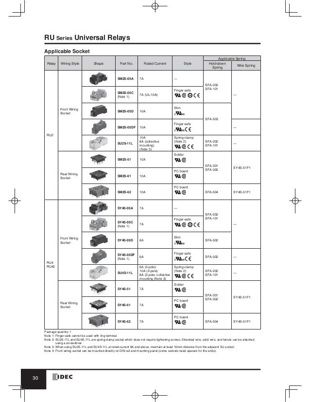
Din rail mount socket comes with two horseshoe clips. A complete dc voltage is best for the coil power to make sure of stable relay operation.

Relay Fundamentals Kele Com
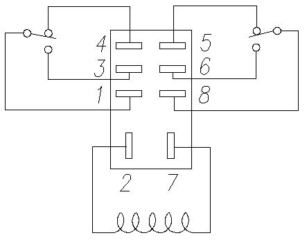
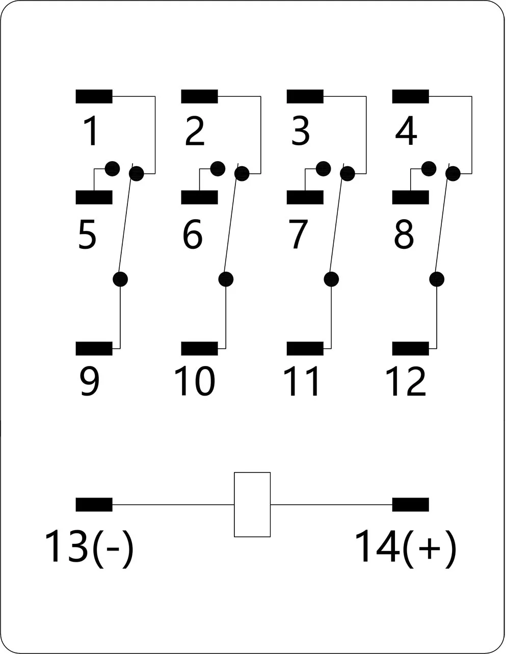
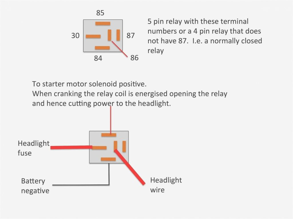
Idec relay wiring diagram. 2 installing and wiring idec smartrelay 2 1 21 installingremoving idec smartrelay 2 2. Replace ment horseshoe clip. At the end of the set time the contacts transfer to the on state. Idec idec main outside www idec rr2p u wiring diagram rh2b u wiring diagram ups va v 50hz circuit diagram transformer v to 30v w 6v spdt relay series spdt relay 12v dc rj2s cl d24 relay idec sy4s 14 pin wiring diagram relay 6v dc. Assortment of 12 volt relay wiring diagram. A wiring diagram is a simplified traditional pictorial depiction of an electrical circuit.
It reveals the components of the circuit as simplified shapes and also the power and signal connections in between the tools. Idec relay wiring diagram wiring diagram is a simplified pleasing pictorial representation of an electrical circuit. 445 latching relay 4 26 446 current impulse relay 4 28 447 interval time delay relay pulse output 4 29. When using a power supply containing a ripple voltage suppress the ripple factor within 5. It shows the components of the circuit as simplified shapes and the aptitude and signal associates surrounded by the devices. Do not use unless you plan to insert pullover wire spring.
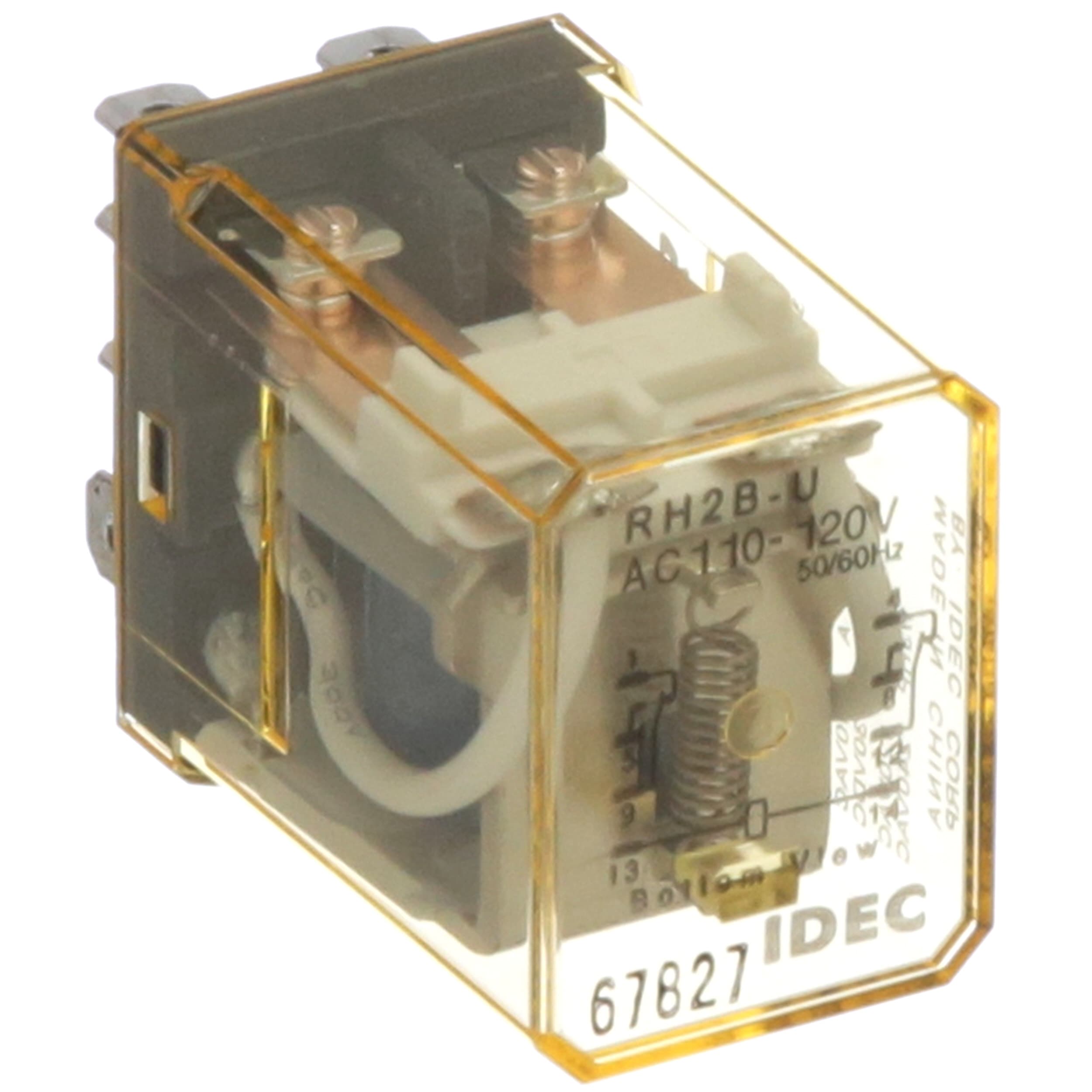
Driving circuit for relays 1to make sure of correct relay operation apply the rated voltage to the relay coil. Idec ru2s c a24 relay plug in relay 10a contact dpdt 24vac coil indicator light dpdt with light no lever dcv coil. 2input voltage for the dc coil. 33 from the circuit diagram to idec smartrelay 3 7 34 the 4 golden rules for working with idec. Relays terminal electrical rating wire size torque din rail sockets sr2p 05 m3 screw with captive wire clamp 300v 10a maximum 2 12 awg 9 115inlbs sr2p 05c m3 screw with captive wire clamp fingersafe 300v 10a maximum 2 12 awg 9 115inlbs sr2p 06 m3 screw with captive wire clamp 300v 10a maximum 2 12 awg 9 115inlbs. Relays sockets timers contactors terminal blocks circuit breakers 800 262 idec 4332 t sa canada 833 timers timing diagrams overview cycle 1 power start off first when voltage is applied to the coil the contacts remain in the off state and the set time begins.
