Youll probably see a thermostat jumper wire connecting the rc and rh terminals. Install and wire as above if using eim.

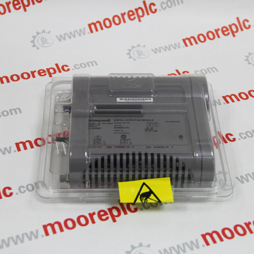
51305072 200 Honeywell I O Card 51305072200 Manufacturer
Honeywell fta wiring diagram. Epks seriesc i0 processor iop and fta model numbers honeywell proprietary iop model iop type and description associated fta model s fta iota description giis cc paih01 hlai hart cc gaix11 giis analog input redundant x cc paih01 hlai hart cc gaix21 giis analog input non redundant x cc paih01 hlai hart cc taix01 ai non. Honeywell fta process manager card. Contains all the essential wiring diagrams across our range of heating controls. C 24 vac common you might see blue purple or brown typically used for this wire. Ap03 400 page 3 advanced process manager smartline 3000 subsystem remote io local control network no. Iv hpm planning 398 standard symbols scope the standard symbols used in this publication are defined as follows.
Our wiring diagrams section details a selection of key wiring diagrams focused around typical sundial s and y plans. Honeywell thermostat wiring diagram 4 wire examples. The honeywell home trademark is used under license from honeywell international inc. Apm is honeywells premier tdcê3000x data acquisition and. Its there so you can supply power to the heating and cooling switches with a single wire which is usually red. For example one digital input processor can handle 24 vdc 120 vac 125 vdc.
If not see pages 13 15. While a separate fta of a given type is required to handle varying field wiring signal levels identical io processors can usually be used. Attention notes inform the reader about information that is required but not immediately evident. Caution cautions tell the user that damage may occur to equipment if proper care is not exercised. The wiring for your honeywell thermostat depends on the functions of your heating and cooling system. Honeywell honeywell honeywell honeywell 13745 figure 1 high performance process manager performing data acquisition and control functions including regulatory logic and sequential control functions as well as peer to peer communications with other universal control network resident devices.
This io approach simplifies system hardware selection and minimizes spare parts requirements. See pages 10 17 for detailed wiring guidelines mcr32387 mcr32389a r c y y2 g w o b w2 aux1 w3 aux2 a l a. Pulse input processorfta 42 serial interface modbus fta 44 serial interface allen bradley fta 44 model numbers 45. Warning warnings tell the reader that potential personal harm or serious economic. Mount the thermostat and wire to c and r terminals of the equipment interface module eim or to a separate 24 volt transformer not provided. But here is a list of the most common wire color mappings as seen in many four wire t stat setups.
The table above provides a more complete list of honeywell thermostat wiring colors and their uses.


