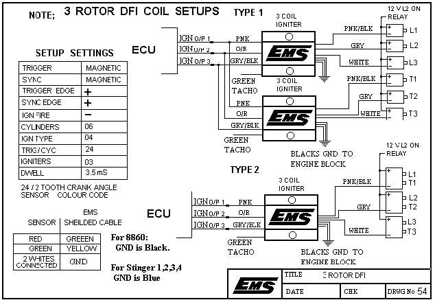
Ecu diagrams em tech series em140160180 em7080 motorsport and stinger motorsport 886068604860 stinger v4 motorsport r tech stinger s2r dualsport dualsport v6 ecus dualsport v5 ecus q and t series ecus ignition system diagrams coil ignition systems igbt ignitors sensor diagrams 4 channel egt modulelsu 49 o2 sensorspressure sensors. Data logging is only available if the ecu is attached for data logging.

Misfire And Backfire Youtube
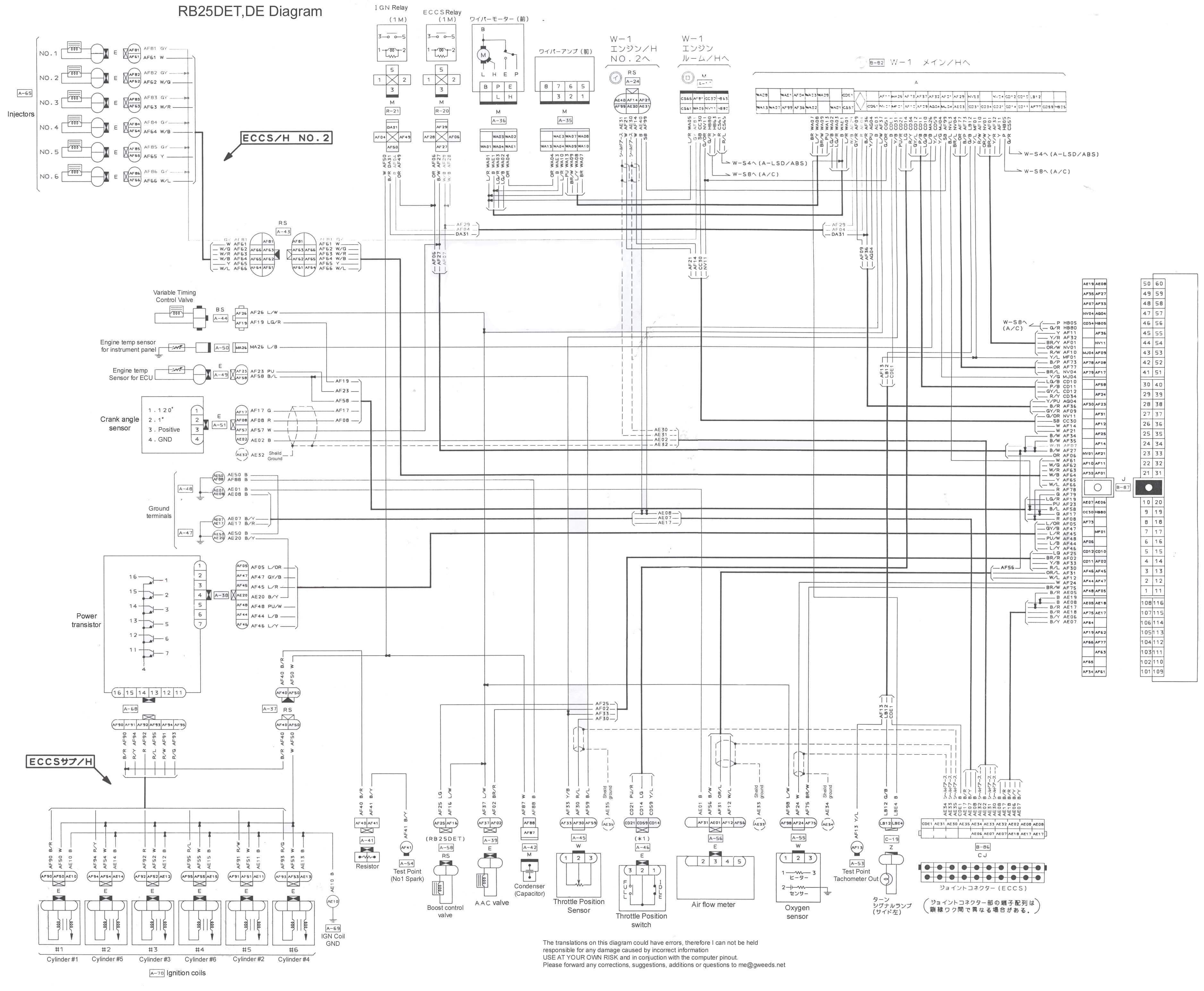
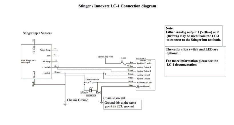
Ems stinger 4424 wiring diagram. Ems stinger 4424 wiring diagram ems stinger 4424 v4 wiring intended for ems stinger wiring diagram image size 618 x 799 px and to view image details please click the image. You can calibrate the sensor to the ecu. That picture ems stinger 4424 wiring diagram ems stinger 4424. The stinger 4 system provides flexible data logging capabilities to assist in gaining the maximum efficiency from an engine. Ems stinger wiring diagram wiring diagram is a simplified within acceptable limits pictorial representation of an electrical circuitit shows the components of the circuit as simplified shapes and the faculty and signal associates together with the devices. The calibration can also be saved as a file and reused on other ems ecus.
Here is a picture gallery about ems stinger wiring diagram complete with the description of the image please find the image you need. It is important that the engine temperature readings be reliable and accurate. See log controls wiring diagrams ecu connection diagram trigger and sync sensor connections hall sensor ems igniter wiring nos wiring diagram. From the thousands of pictures on the internet with regards to ems stinger wiring diagram picks the very best collections using greatest image resolution exclusively for you and now this photos is actually among graphics series in our very best graphics gallery about ems stinger wiring diagrami hope you will think its great. Greyblue and black the ems stinger 4 ecu can use the original engine temp sensor on the engine.


