Wiring diagram 10 0015 10 0016 10 0028 disconnect not shown note. Wiring diagram for models m267 f d267 f and h267 f 1092 thru 0418 004620a run ol.

Zoeller 10 1044 Single Phase 115 200 230 Volt Electrical
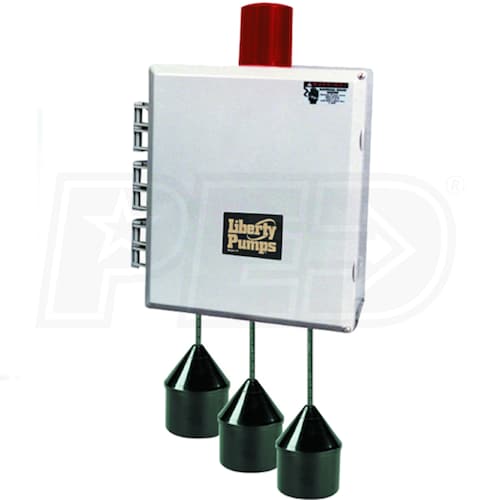
Zoeller 10 1044 wiring diagram. Equipment disconnect 10 0125 only motor contactor all models except 10 1019 and 10 1023 nema 4x watertight enclosure with lockable latch. The zoeller 10 1044 features alarm test and silence switches a high water alarm an alternating mechanism a numbered terminal strip for connecting pumps and variable level float switches integral auxiliary terminal board connections dry contact for remote alarm devices three 20 foot float switches and 3 or 4 variable level float switch. Alarm horn provides audio warning of alarm condition 83 to 85 decibel rating pump run. 10 1136 12 x 10 x 6 575 40 63 c r l u us listed. Zoeller fiberglass or polyethylene basin zoeller float switch zoeller sewage pump electrical alternator control panel indicator lamps inside enclosure toggle switches inside enclosure zoeller unichcek check valve 2 or 3 4 float system alarm bell on both pumps already activated set above override 4 hub inlet alarm override level set. Motor 3 blue red black white green l1 l2 start 1 2 yellow blue red r relay ls s l m267 f e267 f 002395a run.
Zoeller 10 1044 single phase electrical alternator duplex control panel 7 15a nema 4 enclosure an electrical alternator is used on a duplex pump application where automatic electrical cycling of the pump is desired for added protection in residential or commercial applications. Common causes check fuse low voltage overload open open or incorrect wiring open switch impeller or seal bound mechanically defective capacitor or relay when used motor or wiring shorted. N6155 12 115 1 105 70 150 10 4465 16 8 x 8 x 4 10 4464 20 12 x 10 x 6. Switch defective damaged or out of adjustment. Alarm system should be on a separate circuit from pumps. Zoeller fiberglass or polyethylene basin zoeller float switch zoeller sewage pump simplex control panel zoeller unichcek check valve 2 or 3 4 hub inlet alarm level set above on float and below inlet.
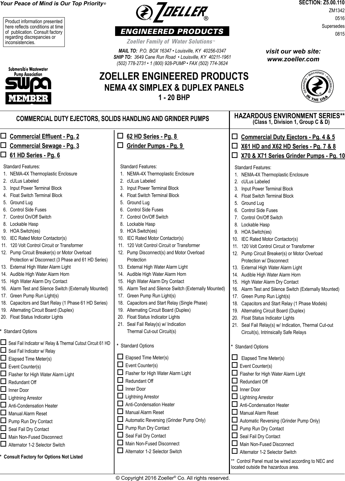
Clear inner door 10 0125 only complete with three 20 6 m control float switches. Motor 3 blue red ac white green l1 2 stat 1 2 yellow blue red r ay ls s l at c white ac wiring diagram for. With one pump operating to handle normal flow a second pump becomes operational in the event the water level. Float assembly held down. Be by zoeller authorized service stations. Zoeller engineered products nema 4x simplex duplex panels 1 20 bhp commercial duty ejectors solids handling and grinder pumps hazardous location series class i division 1 group c d.
Sk313 transformer 115 to 8v or 230 to 8v l1 l2 power utility box alarm bell 8v to control switch see fm0419 for mounting instructions or mechanical alternator 10 0075 with alarm supply zoeller variable level. E6165 1 230 1 102 7 15 10 1037 16 8 x 8 x 4 10 1044 20 12 x 10 x 6 i6185 1 200 1 115 7 15 10 1037 16 8 x 8 x 4 10 1044 20 12 x 10 x 6 e6185 1 230 1 98 7 15 10 1037 16 8 x 8 x 4 10 1044 20 12 x 10 x 6.


