17 ranges model 1812 el a 1812el a 240 vac b 1812el b 230 vac c 1812el c 220 vac d 1812el d 110 vac special features. Automatic data hold function.

Safe Circuit Design Electrical Safety Electronics Textbook
Elcb wiring diagram datasheet. There are many cases in which there is a current flow in the earth wire but the situation is not hazardous in such cases but it gives false trip eg. Digital elcb tester 7 functions. When a live wire comes in contact with neutral wire short circuit will occur hence elcb will not trip because there will be no current in the earth wire. A leaking current through earth terminal is probably more dangerous than a short circuit in a domestic wiring. If the voltage of the equipment body is rise by touching phase to metal part or failure of insulation of equipment which could cause the difference between earth and load body voltage the danger. An elcb is a specialised type of latching relay that has a buildings incoming mains power connected through its switching contacts so that the elcb disconnects the power when earth leakage is detected.
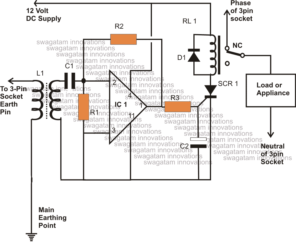
Elcb wiring connectionenergy meter connectionhouse wiringelcb installation an earth leakage circuit breaker elcb is a safety device used in electrical installations with high earth impedance. Circuit diagram using transistors. This figure shows a wiring diagram for the 5094 ia16 an d 5094 ia16xt modules. The elcb detects fault currents from live to the earth ground wire within the installation it protects. A simple elcb circuit is discussed here. An elcb is a specific type of latching relay that has a structures incoming mains power associated through its switching contacts so that the circuit breaker detaches the power in an unsafe conditionthe elcb notices fault currents of human or animal to the earth wire in the connection it guards.
If sufficient voltage appears across the elcbs sense coil it will switch. A short circuit hazard is visible and mostly tackled through a fuse or a circuit breaker unit. Accurate digital readout of disconnection time. As it is assumed that in normal operating conditions the current goes through the phase wire will be returned via neutral wire if theres no leakage in between. 2 lines x 16 characters lcd. Voltage elcb contains relay coil which it being connected to the metallic load body at one end and it is connected to ground wire at the other end.
You must connect a 120v ac power source to the left sa terminals to provide field side power. Lightening strike current starts. Single phase residual current elcb. Low voltage operating and communica tions power for the modular boards is provided through the wiring schemes. Schematics and diagrams and this sheet. The polarity of the phase winding and neutral winding on the core is so chosen that in normal condition mmf of one winding opposes that of another.
5094 ia16 and 5094 ia16xt wiring diagram this figure shows a functional block diagram for the 5094 ia16 and 5094 ia16xt modules. If ample voltage seems across the elcbs sense coil it will turn off the power and remain. The boards that generate low voltage operating and communications power depend upon the individual control system refer to the schematics and diagrams on this sheet.


