The danger isnt fire. It is unusual for.
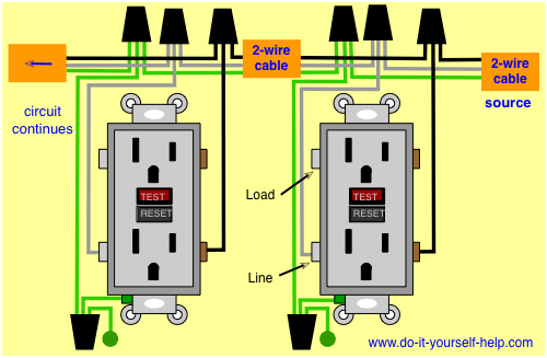
Wiring Diagrams For Electrical Receptacle Outlets Do It
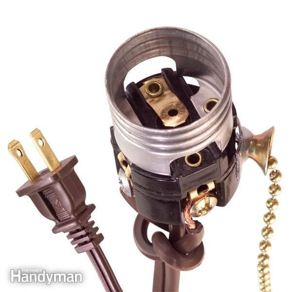
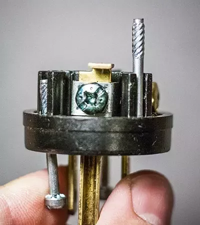
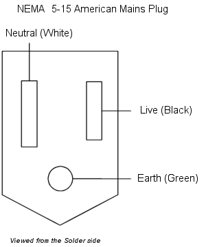
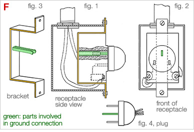
Edison plug wiring diagram. The key is to make sure you connect the wires to the proper terminals in the plug. Wiring a new plug isnt difficult but its important to get the hot and neutral wires connected to the proper prongs. As an example consider two dry cells each 15 volts connected in series as shown above. While most designations have been adopted by various industries some of these configurations have never been manufactured. Dont use this receptacle when no ground wire is available. A grounded contact at the bottom center is crescent shaped.
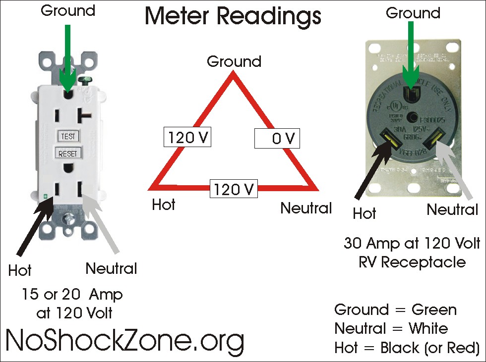
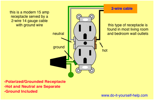
Collection of onan generator wiring diagram. This is a standard 15 amp 120 volt wall receptacle outlet wiring diagram. It reveals the components of the circuit as streamlined forms and the power and signal links in between the tools. The size and type of the customers load must warrant such an installation. Now imagine two lamps each 15 volts and equal current. This is a polarized device.
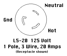
The voltage between legs a and b is 30 volts while the voltage between the neutral and either leg is 15 volts. For example the 5 in the common 5 15 represents 3 wire 125v and the 15 represents 15 amp. This is the edison 3 wire system which is used in homes. The long slot on the left is the neutral contact and the short slot is the hot contact. The worry is that a miswired plug poses a fairly serious shock hazard. A wiring diagram is a simplified traditional pictorial depiction of an electric circuit.
Service voltages higher than 480 volts are available only by negotiation with the company. Wire a plug to maintain correct polarity. 120240 volts 3 wire single phase 240 volts 3 phase 3 wire 120240 3 phase 4 wire 120208 3 phase 4 wire 277480 volts 3 phase 4 wire.
