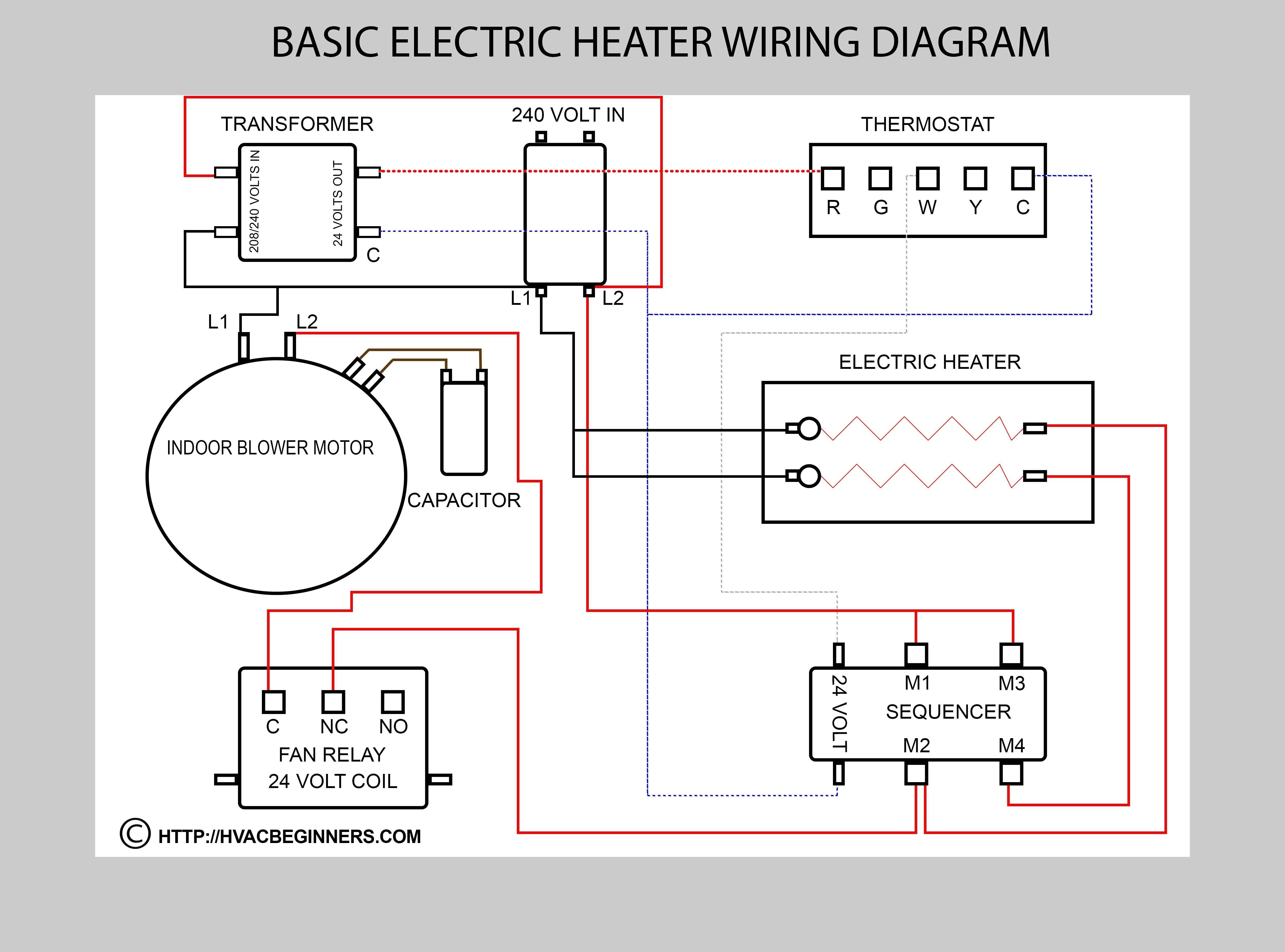
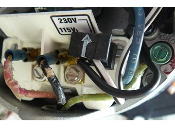
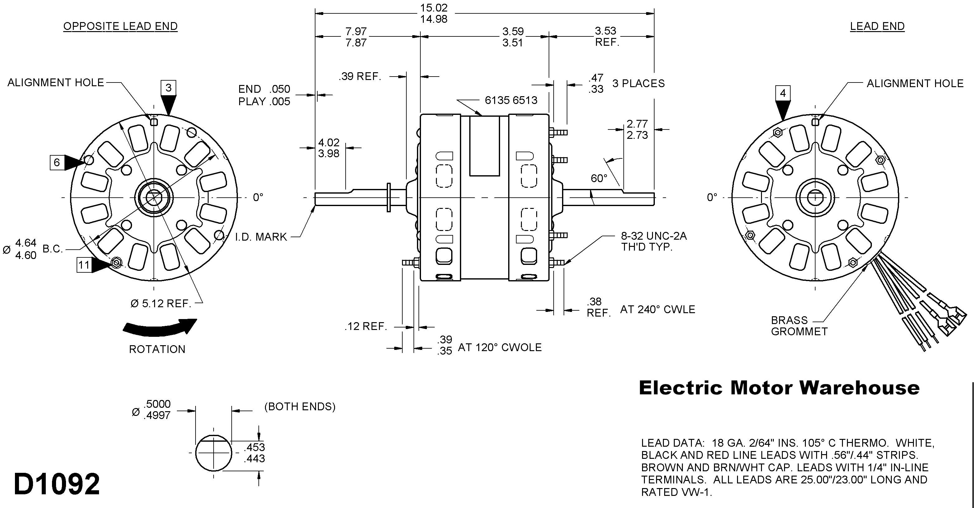
September 18 2018 by larry a. You should find the series and parallel connections on a diagram affixed to the inside of the terminal box cover.

Bx 6183 Motor Wiring Diagram On Emerson Electric Motors
Century electric motor wiring diagram. Century ac motor wiring diagram regarding century ac motor wiring diagram image size 436 x 300 px and to view image details please click the image. Smith uses cx to identify its. This pocket manual is designed for one purpose to make it simple for you to. If on the other hand the motor diameter is less than seven inches and has a terminal board it is most likely a single phase motor. Adjoining cable courses might be revealed around where certain receptacles or fixtures need to be on an usual circuit. Here is a picture gallery about century ac motor wiring diagram complete with the description of the image please find the image you need.
Century electric motor wiring diagram marathon motors for in blurts building circuitry representations show the approximate locations and interconnections of receptacles lights and irreversible electrical services in a building. If you cannot a century ac motor wiring diagram for 115 or 230 volts can be found online. It shows the parts of the circuit as simplified shapes as well as the power as well as signal connections between the tools. Variety of century ac motor wiring diagram 115 230 volts. Century 2 speed motor wiring diagram architectural electrical wiring diagrams show the approximate areas and also affiliations of receptacles lights as well as permanent electrical services in a structure. Of most three phase motors are single colors not multiple colors and usually identified with numbers.
Three phase see below single voltage. Each part should be placed and linked to different parts in specific manner. Century motor wiring diagram century 9723 motor wiring diagram century ac motor wiring diagram 115 230 volts century ac motor wiring diagram 115 volts every electrical structure is made up of various different components. Smiths line of century motors. A wiring diagram is a streamlined conventional photographic representation of an electric circuit. Adjoining wire courses could be shown roughly where specific receptacles or fixtures need to be on an usual circuit.
Occasionally the wires will cross. For wiring a single phase motor the most important objective is to distinguish the starting. The electrical design of the motor is shown by its type. However it doesnt imply link between the wires. According to earlier the lines in a century electric motor wiring diagram represents wires. Electric motor wire marking connections.
For specific leeson motor connections go to their website and input the leeson catalog in the review box you will find connection data dimensions name plate data etc. The wires are color coded and the terminals are numbered. It all rides on circuit that is being constructed. Injunction of 2 wires is generally indicated by black dot at the intersection of 2 lines.


