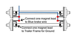
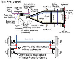
Only the blue brake and white ground wires are different. Extrapolate the same expansion for additional axles.

Installation Of The Dexter Electric Trailer Brake Assembly Etrailer Com
Dual axle trailer brake wiring diagram. This report will be talking wiring diagram for tandem axle trailer with brakes. These 2 wire diagrams fit the needs for most trailers. It is important to note that the white wire is the ground wire you will notice this even when you buy lights. Typically trailer wiring is color coded. Typical trailer wiring diagram and schematic. This car is designed not just to travel 1 place to another but also to take heavy loads.
It reveals the elements of the circuit as simplified shapes as well as the power and also signal connections between the gadgets. A lot of led lights come with black and white wires and people can easily confuse the black wire for the ground. The other wire from each brake magnet will ground to the trailer frame. 28 impressive how much to install electric brake controller. A wiring diagram is a streamlined conventional photographic depiction of an electrical circuit. A faulty and unsecured ground wire is often the.
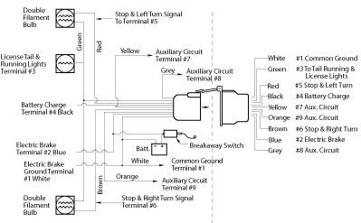
It reveals the parts of the circuit as streamlined forms as well as the power and signal connections in between the gadgets. Wiring diagram for tandem axle trailer best breakaway kit. Assortment of electric trailer brake wiring schematic. Wiring diagram for tandem axle trailer new wiring diagram trailer. Variety of 2 axle trailer brake wiring diagram. 2 axle trailer brake wiring diagram sample wiring diagram for tandem axle trailer valid trailer brakes wiring.
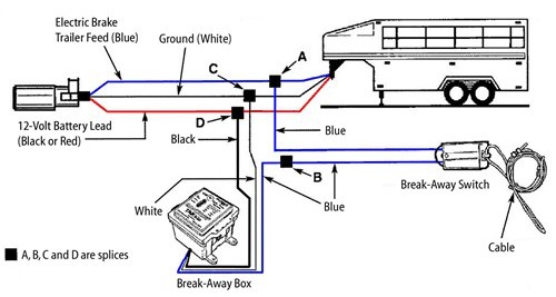
I have attached a drawing that shows how the wiring is typically run for brakes on a trailer. Wiring diagram for tandem axle trailer with brakes wiring diagram for tandem axle trailer with brakes people comprehend that trailer is a vehicle comprised of quite complicated mechanics. The brake circuit is usually a blue wire which travels to each brake magnet where it is attached to one wire from each brake magnet. A wiring diagram is a streamlined conventional pictorial representation of an electric circuit. The diagrams below show the typical trailer wiring for 4 pin flat connectors all the way to 7 pin round connectors. The image above shows a single axle trailer and the next image shows wiring for tandem axles.

