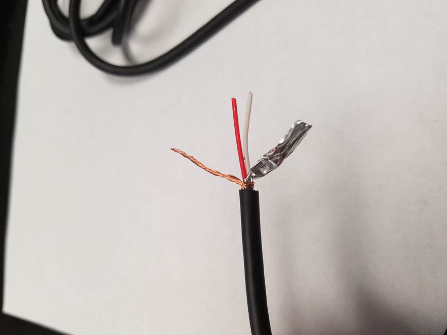
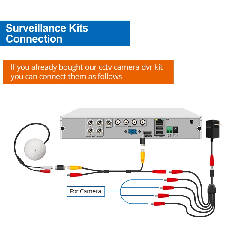
More stars below means better quality wire. In this video we show you how to install a cctv microphone to your cctv system.
Home Video Surveillance Wiring Diagram Home Wiring Diagram
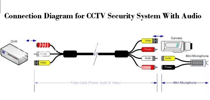
Cctv microphone wiring diagram. The methods used here to attach the rca connector is to attach a crimp on f connector to the cable then screw on a f to rca male screw connector. It shows the elements of the circuit as simplified forms and also the power and also signal links between the gadgets. Use the second drop down list to change the type of wire. Please note that these instructions are the same for cat 6 cable and and other type of 4 twisted pair network cable. This enables the microphone to connect to the idvr pro hd surveillance dvr and a power supply box. Cat 5 wiring diagram crossover cable diagram.
We will continue to try to get all the information that we can listed on this page. Mic wiring can be frustrating enough but when you cant find the right wiring info it is just impossible. You may decide to go with a traditional analog system hd sdi hd cvi or even an ip network based security products. May 7 2013 diagram of cctv installations wiring diagram for cctv system dvr h9104uv as an example. Use the first drop down list on each component to connect to a different component. Radio mic wiring diagram.
A wiring diagram is a streamlined traditional pictorial depiction of an electric circuit. Below is a wiring diagram when using an ip. Today there are a lot of options when it comes to choosing a quality cctv security system. If your ip security camera has rca audio input rather than a two lead wire then the wiring setup is slightly different. Cctv installation and wiring options. In the above wiring diagram a male rca connector is attached to each end of the rg59 coax.
Click the buttons at the top to add audiovideo components to the diagram. The list below offers some microphone wiring information. Cctv microphones httpwwwcctvtekcoukgroupscctv microphones call us. Collection of cctv camera wiring diagram. Wiring setup for ip camera with rca audio input. To configure the camera to detect the external microphone follow instructions in the section enabling audio input on an ip camera.
The chart and image above are correct for these models. It contains library of vector cliparts of video and tv devices and different digital gadgets for drawing such illustrations basic cctv system diagram. Click or to add or remove outputs from a component. This cat5 wiring diagram and crossover cable diagram will teach an installer how to correctly assemble a cat 5 cable with rj45 connectors for regular network cables as well as crossover cables. One thing all of these options have in common is you will probably have to run some sort wire to the cameras. Conceptdraw diagram enhanced with audio video media solution is a helpful tool for illustration of a cctv network.


