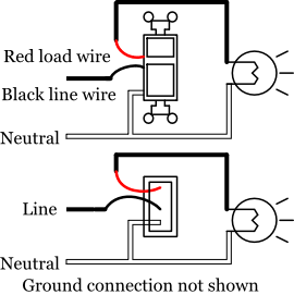
A wiring diagram is a simplified traditional pictorial representation of an electrical circuit. With all the assist of this e book you can easily do your own personal wiring tasks.

What Relay To Use D I Y Kit Uk420
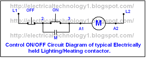
Timer and contactor wiring diagram. Wiring diagram lighting contactor with photocell wiring diagram contactor wiring diagram. This is assuming the timer contact is maintained the whole time you want your lights to be on. With help of following timing diagram we can easily understand working of timer. Timer has two element timer and relay. Otherwise the arrangement wont function as it. When we give supply to timer timer run and after completing set time t timers relay on.
If you have a different voltage coil you still wire it the same one leg goes to a2 and stays there other leg goes through your timer and back to a1. Timimng diagram of timer. It reveals the elements of the circuit as streamlined forms and the power and also signal links between the gadgets. Pdf contactor wiring diagram with timer. Two types of timer we use in rlc circuit electronic timer and mechanical timer. A simple circuit diagram either of the two start buttons will close the contactor either of the stop buttons will open the contactornote that one one of the contactor acts as a switch for the start button.
Contactor breakers limit switch no static control standard elementary diagram symbols. The contactor will pull in when it has the correct voltage across a1 and a2. Timer module to dilm38 to dilm38. Collection of ac contactor wiring diagram. Youll be able to often rely on wiring diagram as an crucial reference that may assist you to save money and time. 6 motor contactor j7kn wiring diagrams coil circuit terminal marking contactors.
The diagram symbols in table 1 are used by square d and where applicable conform to nema national electrical manufacturers a ssociation.


