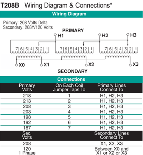
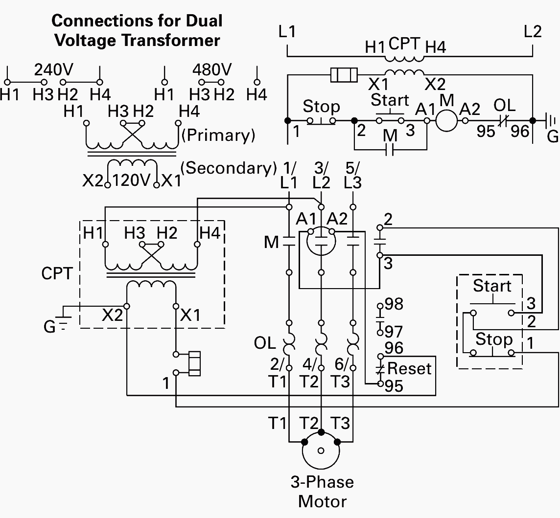
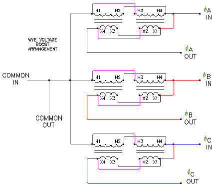
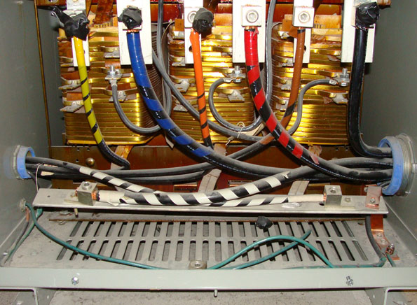
45 kva transformer wiring diagram gallery wiring diagrams kva transformer 45 electrical best 75 diagram and. A wiring diagram is a streamlined standard pictorial depiction of an electric circuit.

Hammond Sg3a0030kb Transformer Ht5695
45 kva transformer wiring diagram. Variety of 45 kva transformer wiring diagram. Ampskva calculator wiring diagram selector. A transformer can supply its rated kva load output to a load with a specified amount of harmonic content. Ex45t3h doe 2016 lv xfmr 3 phase 45kva 480 delta 208y120 al 150c rise 220c ins. Wellborn variety of 45 kva transformer wiring diagram. November 8 2018 by larry a.
Resume 45 beautiful 480v to 120v transformer wiring diagram high. This is very similar to the standard 10 foot tap rule. 15 30 45 75 1125 150 225 300 500 k1 k4 k13 k20 115c n 208δ 480y 480δ 208y 480δ 240δ120lt 480δ 380y219. The point where all the wye legs come together is the x0 point on the transformer diagram. For a 1125 kva transformer 135a125169a so use a 20 awg conductor rated 175a at 75c per table 31016. The purpose of the equipment grounding conductor for the transformer primary circuit is to connect all conductive material that encloses the transformers primary ungrounded circuit conductors or electrical equipment which is required to create an effective ground fault current path.
The square d distribution transformer is designed to supply power throughout the building. Distributes a voltage higher than required by the load to limit wire losses and voltage drop. Size the equipment grounding bonding conductor for the transformer primary based on the size of primary protection device per 250122a. The way that you can get 277v power out of the secondary as it is noted on the transformer data plate is to use that x0 point. A wiring diagram is a simplified traditional photographic depiction of an electrical circuit. A 45 kva transformer protected on the supply side with a 70 ampere circuit breaker multiplied by the ratio of 23 would result in the secondary conductors having a minimum ampacity of 161 amperes or 110 the size of the primary overcurrent device after the voltage ratio is applied.
The only item that i am not certain of is the grounding of the x0 point on the secondary of the transformer. The transformer permits multiple voltages to be leveraged in the design of the system. It reveals the components of the circuit as streamlined forms as well as the power as well as signal connections in between the tools. Wiring diagrams transformer wiring auto wiring diagrams instructions. 480 to 120 transformer wiring diagram wiring data. Advantages to designing a system with low voltage transformers.
It shows the elements of the circuit as simplified shapes and the power as well as signal links between the devices.


