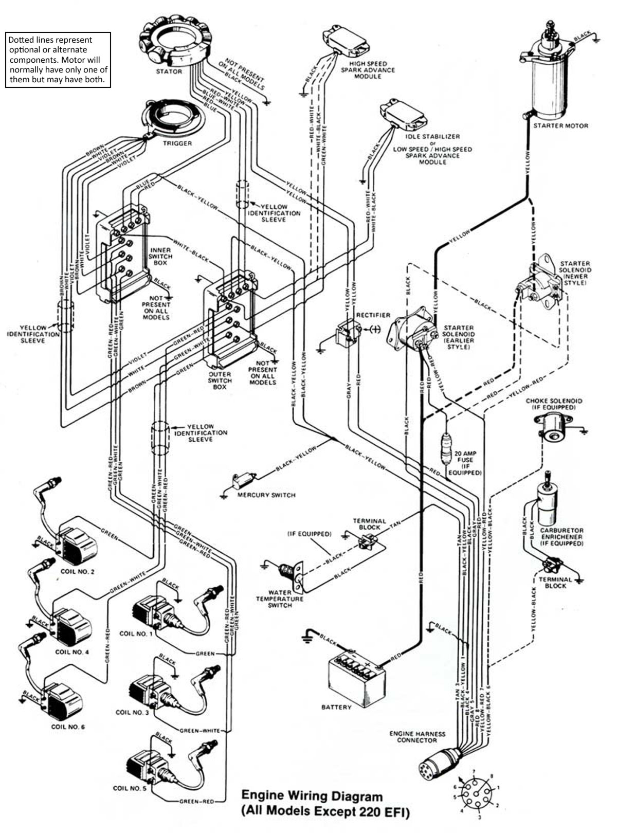
Yamaha 40 hp wiring diagram wiring diagram database. Receiving from point a to aim b.
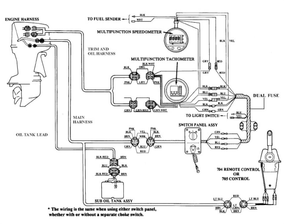
34 Yamaha Outboard Tachometer Wiring Diagram Wiring Diagram
Yamaha analog tachometer wiring diagram. Multi function tiller handle kit for japan. Pole number set up. Genuine yamaha conventional digital and analog gauges offer classic simplicityno touchscreens and no programming. Black wire for signal connected to negative of coil to allow tacho to sense engine speed. The round gauges feature the similar shape design as conventional. There is an industry standard set of wire codes in general use by most manufacturers except yamaha.
Use a wiring kit to connect the tachometer to the plug in connector on the remote control or accessory electrical cable. Here is a listing of common color codes for yamaha outboard motors. Yamaha outboard wiring diagram pdf. Wiring diagram yamaha gauges. Yamaha f40feht f40fehd pdf user manuals. A wiring diagram is a simplified standard photographic representation of an electric circuit.
Colors listed here may vary with year model but in general should be a good guide when tracing yamaha wiring troubles. I am looking for wiring diagrams for ignition and gauges for all of the yamaha digital display multi function gauges operate the same. Variety of yamaha outboard tachometer wiring diagram. I purchased 2 yamaha gauges and a friend of mine told me he could see the colors match up but i dont have any wiring diagrams to look at. For garcons analog tachometer like the above photo tachometer wiring connections are as below. Just critical engine and systems data for single engine mechanical control rigs delivered in clean designs.
Multifunction digital and pro series ii and pro series analog gauges. Green wire to negative or body or ground wire. Here is a listing of common color codes for yamaha outboard motors. Use plug infuse block kit pn 0173611 when installing tachometer with other accessories. Yellow wire is connected to ignition switch on position to connect to positive. It shows the parts of the circuit as streamlined shapes as well as the power and also signal connections in between the tools.
It reveals the elements of the circuit as simplified forms as well as the power and signal connections in between the tools. Wiring diagram for us 114. View online or download yamaha f40feht f40fehd rigging manual. Use plug in connector kit pn 0174732 when installing tachometer only.


