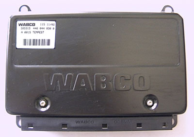
Módulo de control electrónico dewabco abs control module part used wabco abs ecm for freightliner cascadia has no part numbers call the following number for the part. Taken into account when installing wabco vario c abs.

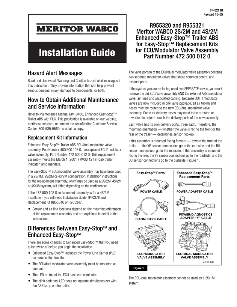
Meritor Wabco Pneumatic Anti Lock Braking Systems Abs For
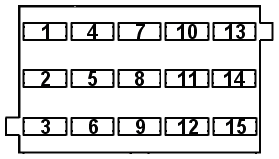
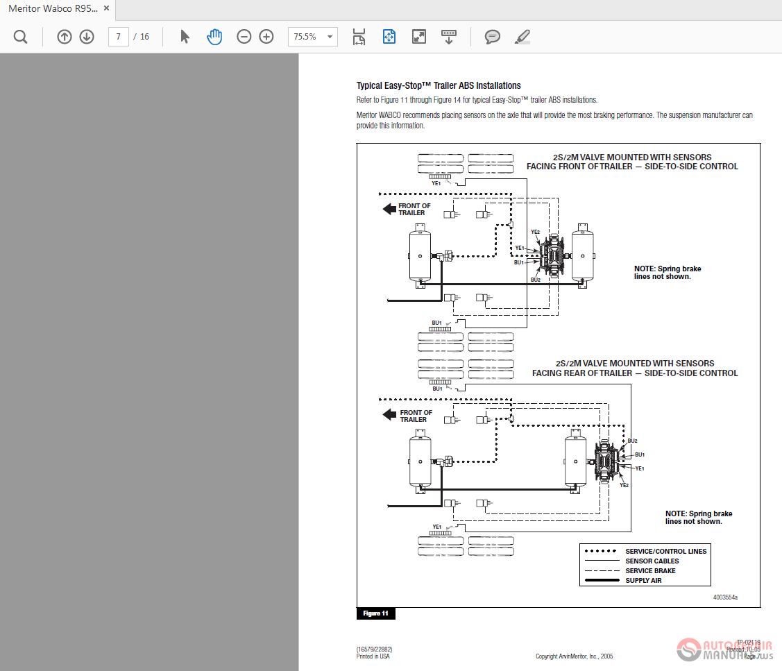
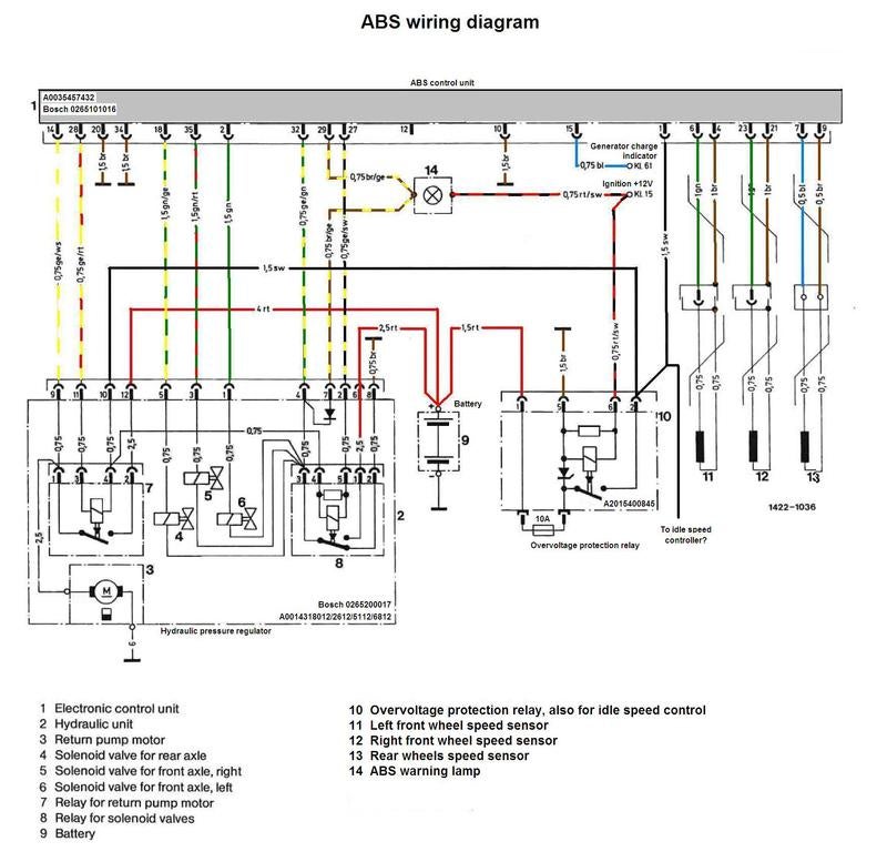
Wabco abs valve wiring diagram. Each component ought to be set and linked to different parts in particular way. If not the arrangement wont work as it should be. 6 appendix ii wiring diagrams 44 meritor wabco maintenance manual mm 0112 revised 07 05 basic ecu cab mounted figure 64 figure 64 back view of harness connector. Ecu wiring diagrams listed by make and model. Standard connection wiring diagramabs troubleshooting for trucks trailers and buses. Not only will it assist you to achieve your desired final results faster but also make the complete method less difficult for everybody.
Drain the air from all system air tanks. Otherwise the structure will not work as it should be. Wabco abs wiring diagram meritor abs valve wiring diagram meritor abs wiring diagram meritor wabco trailer abs wiring diagram every electrical arrangement consists of various different components. Each component ought to be placed and linked to other parts in particular way. Abs abs pressure control valve drive axle right abs electronic control module. Wabco trailer abs wiring diagram meritor trailer abs wiring diagram wabco trailer abs ecu wiring diagram wabco trailer abs module wiring diagram every electric arrangement is made up of various distinct parts.
Wabco abs wiring diagram you will want a comprehensive skilled and easy to comprehend wiring diagram. Locate the correct wiring diagram for the ecu and system your vehicle is operating from the information in the tables below. Pressurized air can cause serious personal injury. Abs valve packages stability control lamp operates correctly. With such an illustrative guide you will have the ability to troubleshoot avoid and total your tasks easily. Abs valve right rear abs valve right front sensor left rear sensor left front sensor right rear sensor tp 1 4 3 6 2 5 iv gnd ov iv gnd ov 10 13 11 14 12 15 17 18 iv gnd ov.
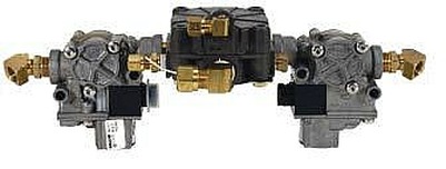
Connect the air supply line to port 1 of the abs valve. Connect the line to the brake chambers to port 2 of the abs disconnect the wiring from the valve.

