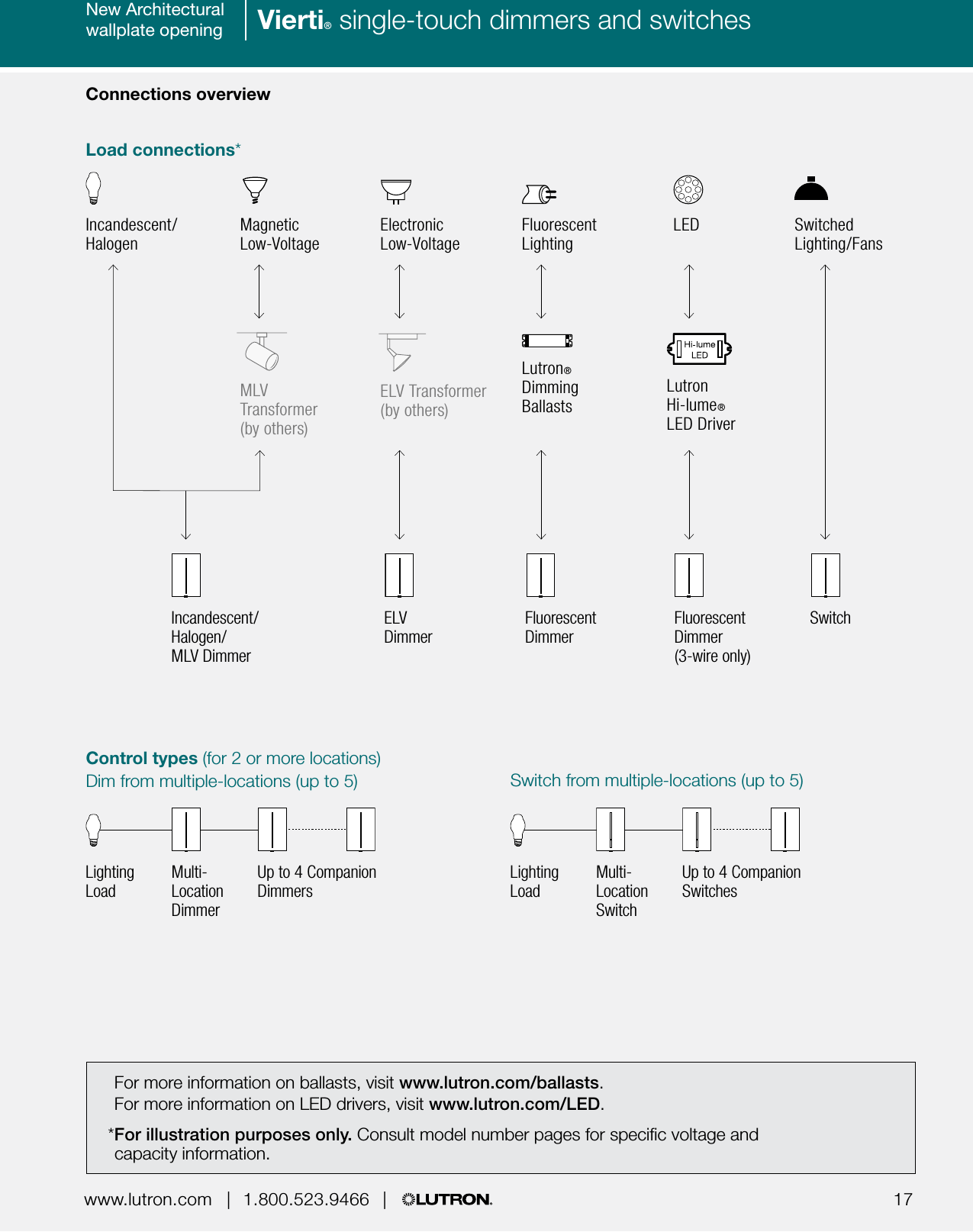
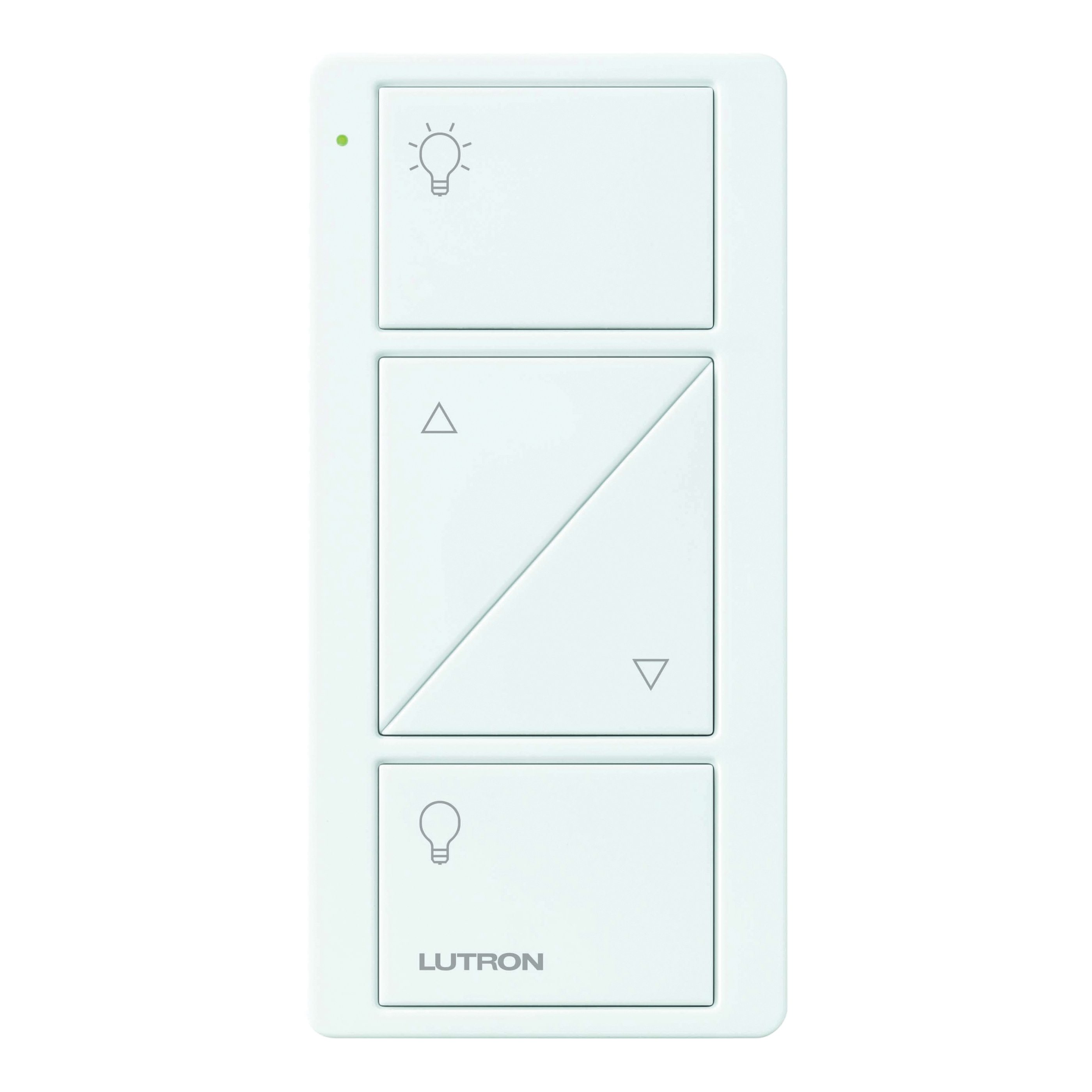
Easily monitor control and optimize a lutron control system from any tablet pc or smartphone. Lutrons new facility management tool empowers you to manage your building from anywhere.
Pagetitle Van Meter Inc
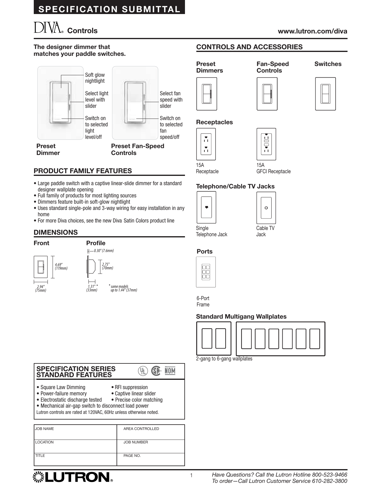
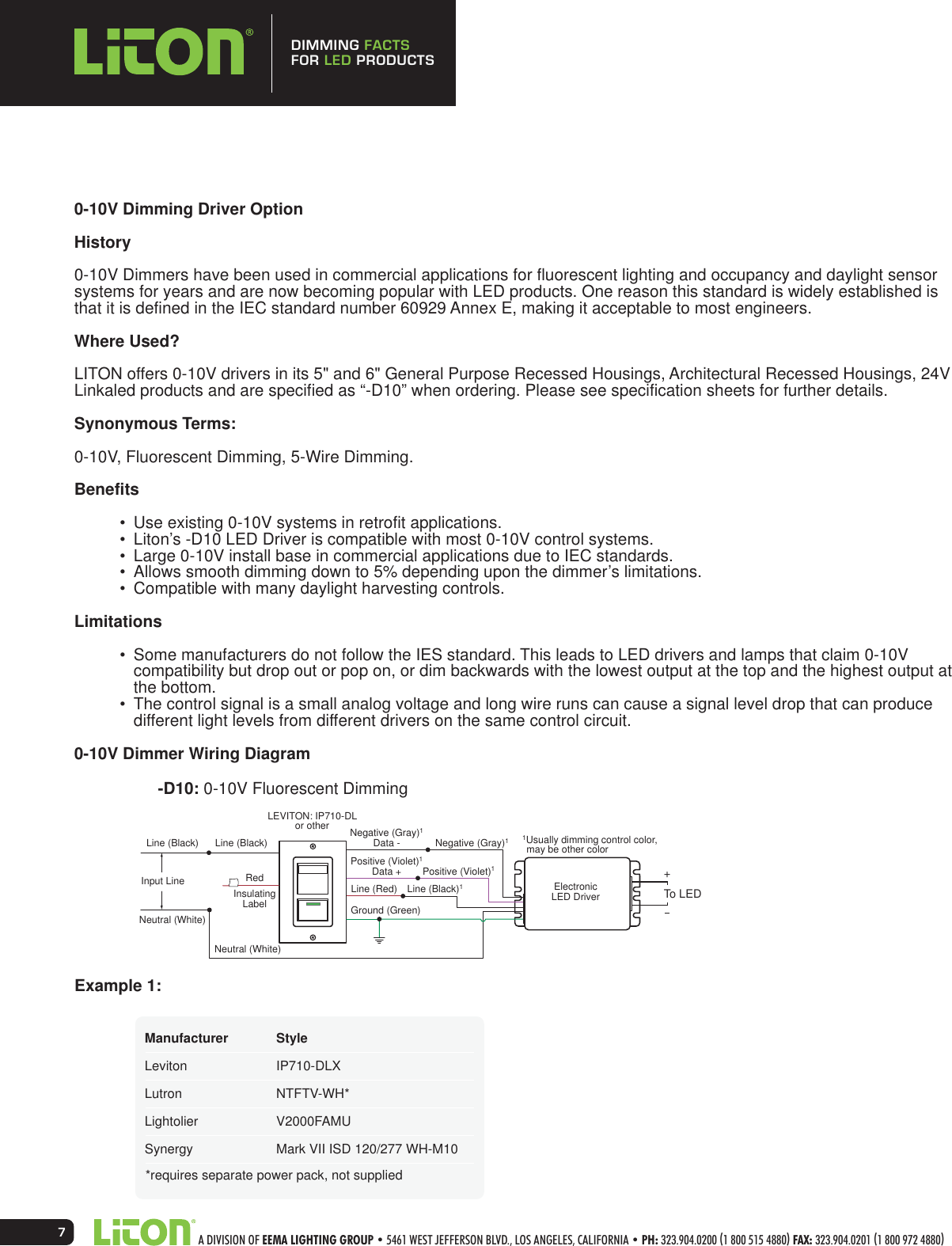
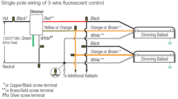
Lutron dvf 103p wiring diagram. L1 h1 is the line hot feed to power the load. Do not use two dimmers in the same 3 way circuit. Wiring diagrams wiring diagram 8 single pole wiring of a 3 way control model dvf 103p dvf 103p 277 wiring diagram 9 3 way wiring model dvf 103p dvf 103p 277 ca 3ps green 120 v or 277 v 60 hz to additional ballasts dimmer orange or brown white black black orange or brown white yellow or orange black blue red line hot neutral. Each feature is designed around what is most important to you how well your building is working. If further information is necessary contact the lutron hotline 1 800 523 9466. Wiring diagram 9 3 way wiring model dvf 103p dvf 103p 277 ca 3psh green 120vac or 277vac 60hz to additional ballasts dimmer orange or brown white black black orange or brown white yellow or orange black hot blue red neutral white violet or blue must use lamp disconnect sockets with magnetic.
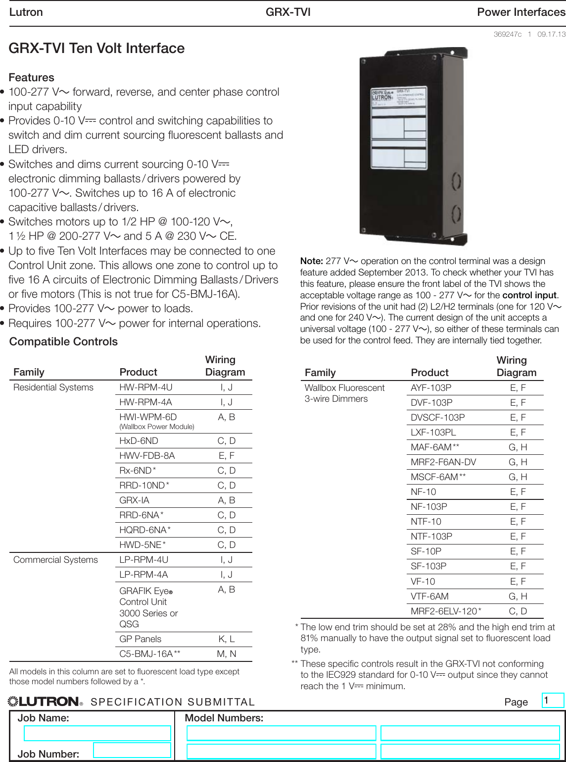
Each feature is designed around what is most important to you how well your building is working. Lutron part number dvf 103p wh item weight 001 ounces product dimensions 175 x 22 x 425 inches item model number dvf 103p wh is discontinued by manufacturer no color white style dvf 103p wh finish white voltage 120 volts wattage 1000 watts amperage capacity 8 a item package quantity 1 number of pieces 1 switch type 3 way plug profile. Call the lutron hotline 800 523 9466 to ordercall lutron customer service 610 282 3800 green 120vac or 277vac 60hz to additional ballasts dimmer orange or. Ayf 103p dvf 103p and dvscf 103p operate at 120v only. Lutron grx tvi power interfaces 369247e 4 070716 wiring diagrams each terminal can accept up to two 12 awg 25 mm2 conductors. Easily monitor control and optimize a lutron control system from any tablet pc or smartphone.
Lutrons new facility management tool empowers you to manage your building from anywhere. Ayf 103p 277 dvf 103p 277 and dvscf 103p 277 operate at 277v only. Wiring diagrams wiring diagram 8 single pole wiring of a 3 way control model dvf 103p dvf 103p 277 wiring diagram 9 3 way wiring model dvf 103p dvf 103p 277 ca 3ps green 120 v or 277 v 60 hz to additional ballasts dimmer orange or brown white black black orange or brown white yellow or orange black blue red line hot neutral. L2 h2 on the control circuit terminals supplies operating power for the ten volt interface. Wiring diagrams wiring diagram 8 single pole wiring of a 3 way control model dvf 103p dvf 103p 277 wiring diagram 9 3 way wiring model dvf 103p dvf 103p 277 ca 3psh have questions. In multi phase applications use a separate neutral for each dimmer circuit.
Wiring diagrams a c e g i and m show a.
