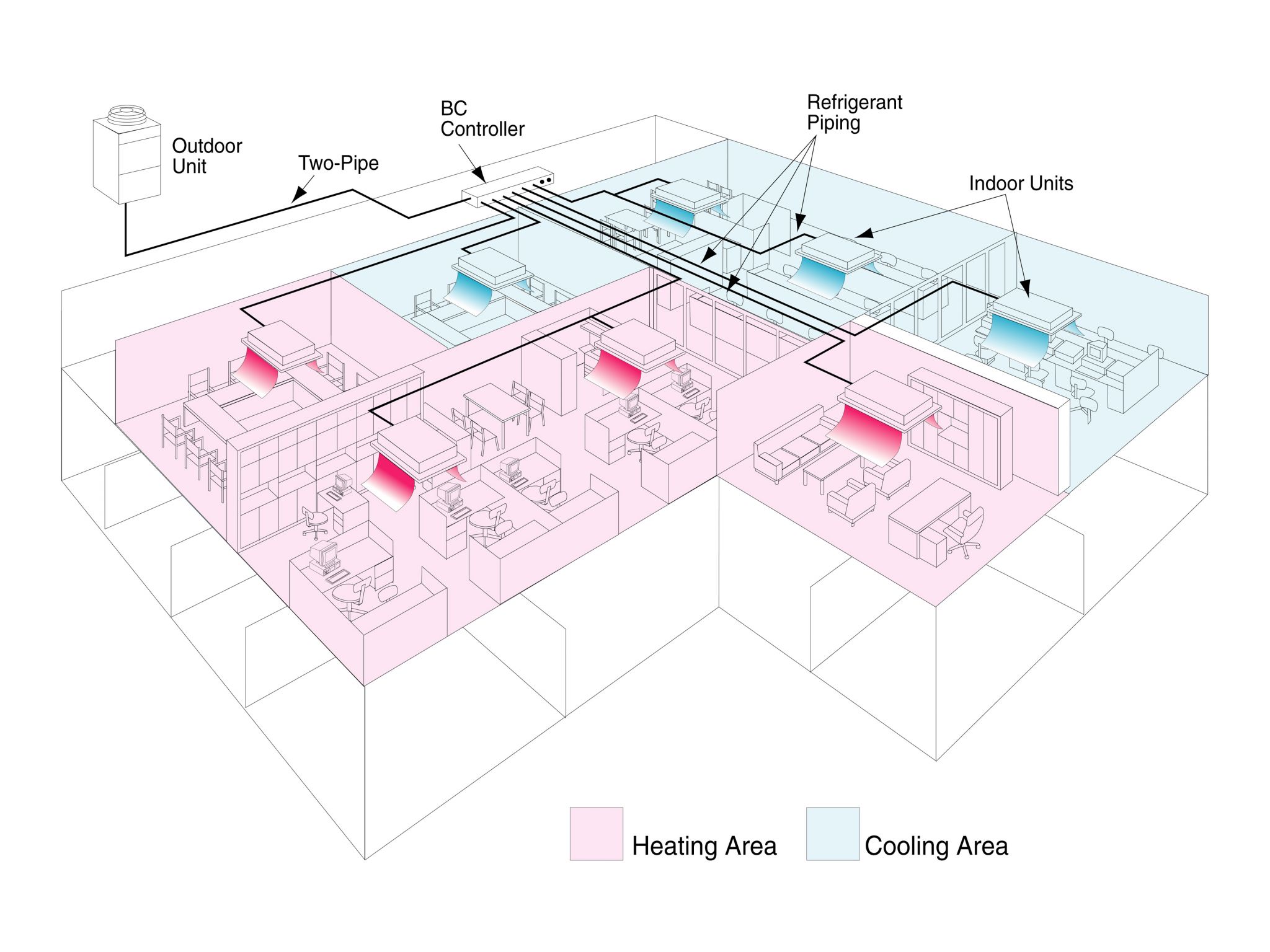
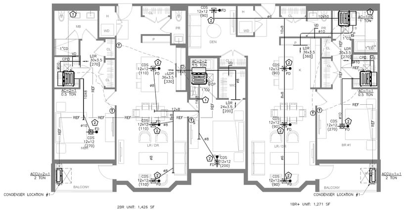
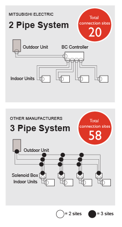
The control wiring is very simple its basically two 18 gauge wires that go from the thermostat to the fan coils wire 1 so that each zone will have a wire from the thermostat to the fan coilone controller thermostat can control more than one indoor. Variable refrigerant flow system outdoor unit series february 2013 vrf svn34a en installation operation and maintenance models.
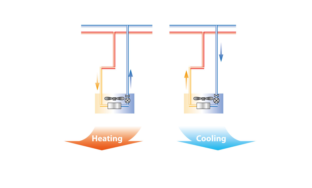
Vrf Technology Details Toshiba Klima
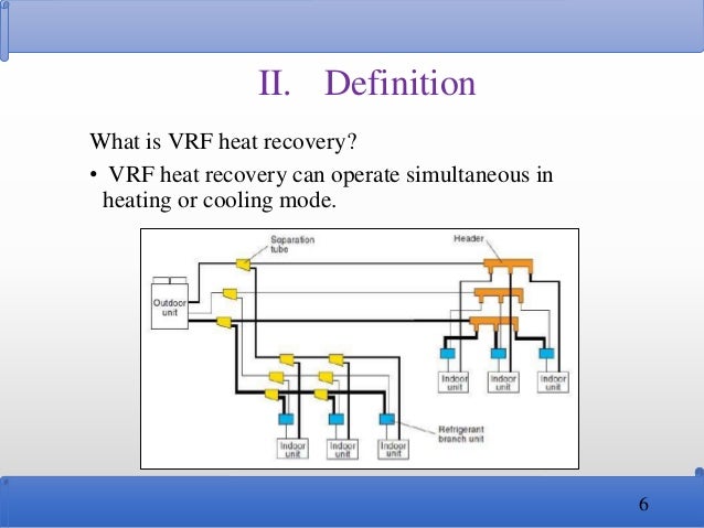
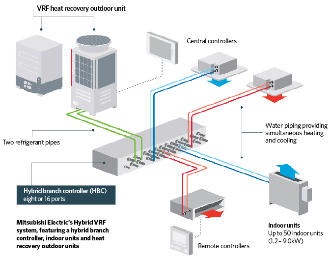
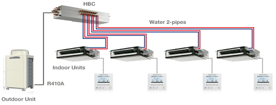
Vrf system wiring diagram. Storage of data on system operation status on a pc allows access even from off site. All field wiring must be. Proper field wiring and grounding required. Failure to follow code could result in death or serious injury. Cooling switch remote control wiring between the units sold separately is connected. Vrf vrv simple control wiring for a heat recovery system using single port branch selector boxes.
Page 13 installation field wiring cooling only heat pump 2 1 2 field line connection. This control wiring layout is similar amongst the other vrf manufactures. Vrf system control wiring. Hp 208230 v hp 460 v hr 208230 v hr 460v 4tvh072b300nb 4tvh072b400nb 4tvr072b300nb 4tvr072b400nb 4tvh096b300nb 4tvh096b400nb 4tvr096b300nb 4tvr096b400nb 4tvh120b300nb 4tvh120b400nb 4tvr120b300nb. 4tvh0036b100nc 4tvh0048b100nc 4tvh0053b100nc vrf svn33d en. Variable refrigerant flow vrf system single phase outdoor unit series models.
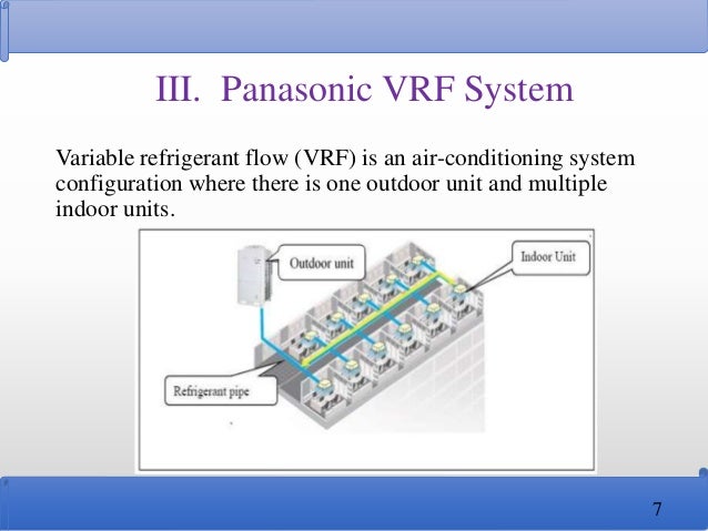
Up to 400 indoor units a single vrf network system can be controlled and monitored for large scale buildings or hotels. This vrf system control wiring is for a vrf vrv heat recovery system with single port branch selector boxes. Transmission wiring coolheat selection heatingcooling switching remote control indoor outdoor outdoor outdoor heatingcooling switching remote secure to the lock plate using control cord when a heating the included cramping material. This software can be connected to any point of transmission line with usb adaptor locally purchased the saved data can be displayed.

