Quite apart from the added complications of building a multi screw boat the modeller needs only to purchase fit and maintain one of everything eg. Borders model boat club wiring model boats this article is intended to explain the basics of wiring a radio controlled model boats.

Seaking V3 User Manual Amp Trouble Shooting Hobbywing North
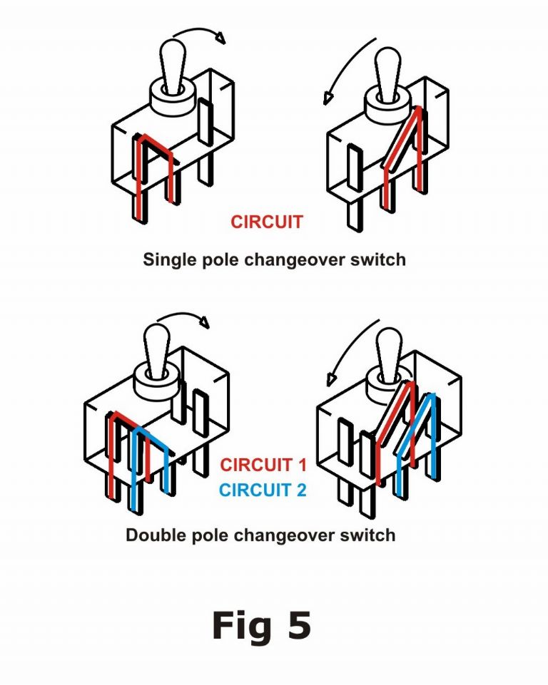
Twin motor rc boat wiring diagram. Single engine 1 starting and 1 house battery. Twin engine 2 starting and 1 house battery. In a radio controlled switch it operates either an electromechanical relay or a semiconductor which in turn switches an external circuit eg. The original remote switch for model boats was a sensitive mechanical type called a microswitch mounted on top of a standard servo. Near finished diy kit of the rc boat without the top shell and water tight covers. Layout of the basic components of the rc boat fig.
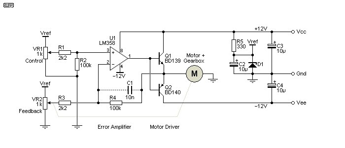
A mini rc boat fig. Motor shaft coupling. For current to flow which does the work a complete circuit must be made from positive back to the negative. Rc boat twin brushed motor twin esc wiring diagram 07112018 07112018 3 comments on rc boat twin brushed motor twin esc wiring diagram very first boat having now got my twin motors each connected up to not easy to remotely diagnose your problem with rc system. The first section discusses the components which may need to be installed the second section addresses the question of what type of wire to use the third section discusses the different types of connector and. Every non engine wire every one should be circuit protected with a fuse or circuit breaker.
At the end of the shaft is the propeller. The grease in the stuffing tube provides lubrication and also prevents water from entering the hull. There is no doubt that the single screw rc model boat is the simplest form of the powered genre. Lights winch motor sound unit. Select from the options below to show the appropriate wiring diagram depending on your particular setup. Daves definitive answer for setting up twin electric motor installations.
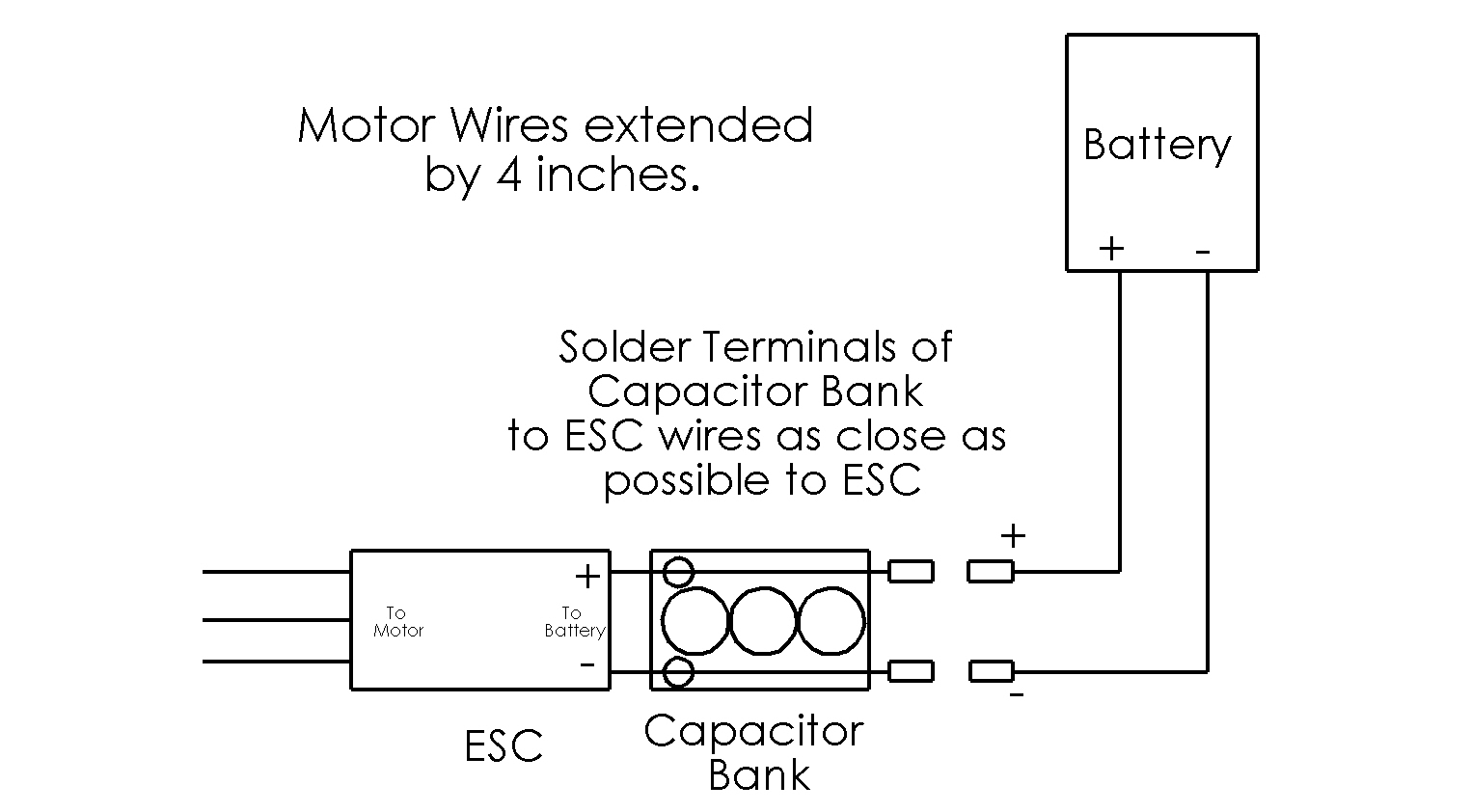
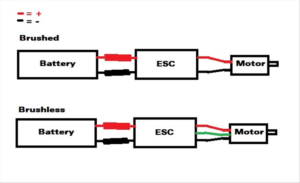
System wiring below is a diagram to show how to wire a typical brushless motor system. Batteries have a positive and negative.
