If you are connecting pin 3 hot gear to a patch bay that is otherwise all wired as normal just reverse the polarity on the cables running between the patch bay and the pin 3 device. Wiring diagram includes the two examples and step by step instructions that will permit you to definitely really construct your venture.

251051d1314585746 Xlr Trs 1 4 Starquad Cable Solder Problem
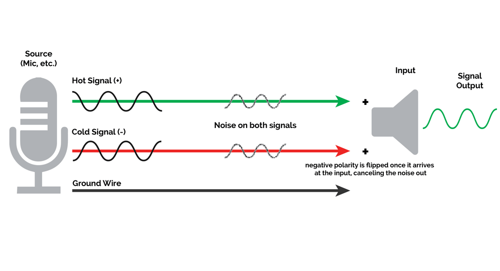
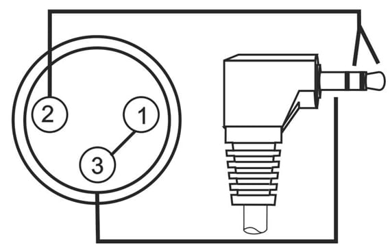
Trs to xlr wiring diagram. This is helpful for each the individuals and for specialists that are looking to learn more on how to set up a operating. A set of wiring diagrams may be required by the electrical inspection authority to approve membership of the address to the public electrical supply system. Balanced xlr wiring diagram wiring diagram database trs wiring diagram. Xlr pin 1 to 14 plug sleeve. Another variant connector is the stereo wired trs tip ring. This wiring configuration gives you a balanced mono audio cable.
Xlr pin 3 to 14 plug ring. Xlr pin 2 to 14 plug tip. Xlr to ts 14 connecting a balanced xlr connector to an unbalanced 14 connector. The typical connector for unbalanced audio is either rca 14 ts tip sleeve and 18 ts. Xlr to 14 trs connector wired for balanced mono the usual way to connect a 3 pin xlr to a 14 trs aka stereo jack plug is to use the following pin allocation. You can actually reverse the wire at either the xlr or trs end but the xlr end is usually easieragain dont reverse both ends or you will be back to normal.
The trs connector can be used for many things including balanced audio sendreturn for insert points and leftright stereo just to name a few. An explanation and diagram showing how to wire an xlr cannon connector to r rca connectors. Phono wiring diagram schema diagram database phono plug wiring diagram xlr to rca wiring diagram fresh xlr trs.


