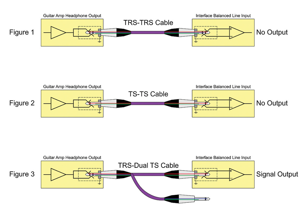
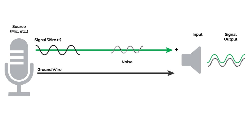
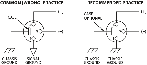
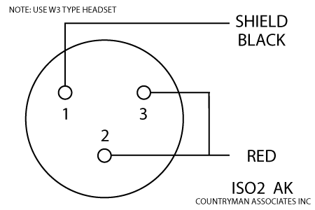
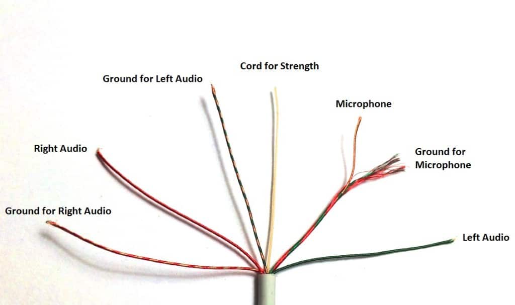
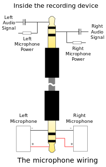
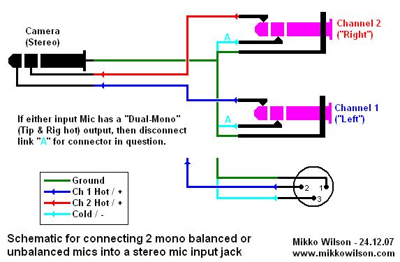
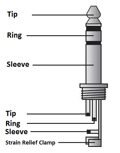
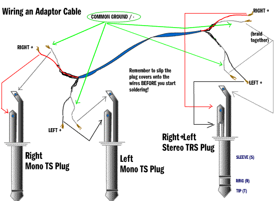
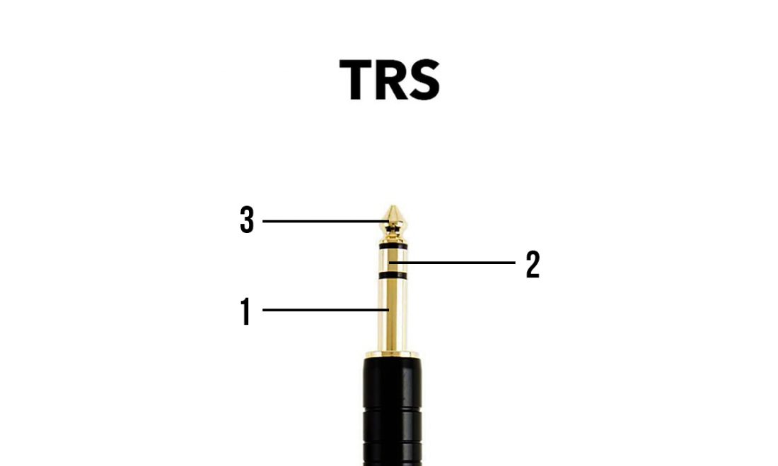
Trs jack wiring diagram data wiring diagram today trs wiring diagram. Trs type male audio jack here in the name of trs t stands for tip r stands for ring and s stands for sleeve these types of audio jacks supports stereo sound and but doesn t supports microphone so using this you can only listen music but can t talk on calls below is the pinout of trs type male audio jack application speakers microphone.

Mic Headphone Jack Wiring Diagram Chevy 2009 Rmnddesign Nl
Trs to ts wiring diagram. This e book even includes recommendations for extra provides that you might need as a way to end your tasks. Wiring diagram also provides helpful suggestions for tasks that may need some extra equipment. Nov 10 trs jack wiring audio making a 4 pole trrs to 3 5mm stereo mic rhjebbushco. An inexpensive pair of earbuds will usually fail sooner or later either where the mm headphone jack plug showing the three connections wiring diagram. Trrrs thanks to ik multimedia for the above diagram which illustrates the do not plug the earbudsmic with trrs into the trs headphone. It was invented for use in telephone switchboards in the 20th century and.
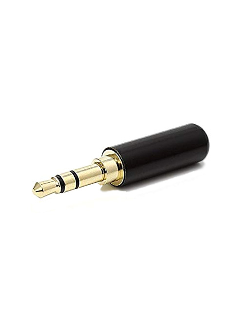
Also for hobbyists 35mm audio jack is a useful components for projects that plug into headphone jacks. It will be capable to provide you with extra gear like. 3 5mm audio jack ts trs trrs type audio jack wiring. A trs connector tip ring sleeve also called an audio jack phone jack phone plug jack plug stereo plug mini jack mini stereo or headphone jack is a common analog audio connectorit is cylindrical in shape typically with three contacts although sometimes with two a ts connector or four a trrs connector. Ts type male audio jack. Types of 35mm jack.
Trrs a ctiaahj wiring standard. There are different types of 35mm audio jack available with different application like ts trs and trrs but the most common that we see in daily life is trs and trrs. 3 5mm trrs jack wiring diagram a pcb layout is the resulting design from taking a schematic with specific components and determining how they will physically be laid out on a printed circuit board.
