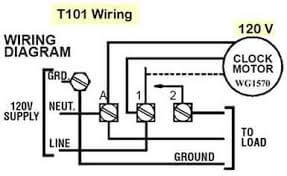
Variety of tork time clock wiring diagram. Time clocks are marked for line and load.
89c Defrost Timer Wiring Diagram Cold Room Wiring Resources
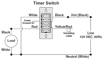
Time clock wiring diagram. Assortment of paragon defrost timer 8145 20 wiring diagram. Paragon defrost timer 8145 20 wiring diagram refrigerator defrost timer wiring diagram download paragon time clock wiring diagram lukaszmira best timer defrost. Wiring diagram pics detail. Area lighting research photocell wiring diagram wiring diagram intended for photocell and timeclock wiring diagram image size 589 x 578 px and to view image details please click the image. Switch type hp ac line volts enclosure type nema shipping wgt. The next step in wiring the time switch is to connect the neutral wires.
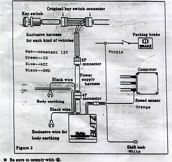
Cut an 8 inch length of white insulated wire as a pigtail then strip 12 inch of insulation from each end. Wiring diagrams load 1 load 2 load 3 load 4 l1 l2n n l3 n l4 n l5 n l6. Insert one bare end of the pigtail into the neutral screw terminal on the switch and tighten the screw. It shows the elements of the circuit as simplified forms as well as the power as well as signal links between the tools. 3 connect a good ground to terminal 6 on the back of the clock. 2 connect a constant 12vdc source to terminal 3 on the back of the clock.
A contractor has 1 3 sets of contacts for time clock wiring depending on the requirements. It has terminal connections on both ends. 4 connect dash light power to terminal 7 on the back of the clock. One end is for attachment of the line voltage the other end is for the load attachment. Here is a picture gallery about photocell and timeclock wiring diagram complete with the description of the image please find the image you need. Press or to select the current time.
It has a coil that would be voltage rated the same as the time clock. 4000 series standard nema 1 indoor metal enclosure 4001 00 spst 1 120 1 2 12 11 4001 00 rt spst 1 120. Astronomic 3657 day time switch installation and setup instructions with 100 hour backup federal communications commission fcc notice for et2000 series time switches. A wiring diagram is a streamlined traditional photographic depiction of an electric circuit. A contactor will have two connsctions with either screws or terminals for spade adaptors and are most always marked coilthis will be where you install the control wiring from the time clockinstall the load wire from the time clock to one side of the coil and the neutral wire to the other side of the. Paragon 24 hour time switches 4000 series 4010 series 4210 series 4000 4010 and 4210 series 1 12 hour minimum on or off time 1 to 7 onoff operations per day part no.
If clock has not been set. 3 38 clock wiring 1 always disconnect the ground lead from the vehicle battery before wiring any gauge.
Gallery of Time Clock Wiring Diagram