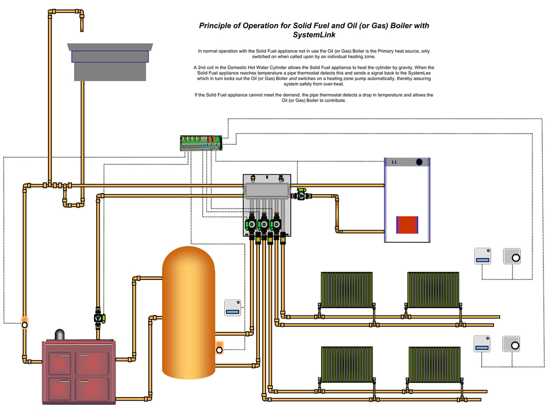
Just connect power boilers thermostats timers. Learn to navigate this systems wiring circuitry and diagram using current flow analysis relay and module operation and neutral switch actuation such as circuit completion.
Feeding Experimentation Device 3 Fed3 Hackaday Io
Systemlex wiring diagram. Four zones two heat sources auxilliary functions. Installation guide wiring plumbing e09. To aid diagram clarity earth connections are not shown but must be installed in accordance with manufacturers instructions example controls wiring schematic with systemlex 1 oil boiler 1 solid fuel stove 2 radiator zones 1 underfloor heating zone 1 dhw zone. Systemlex is a pre confiugured electronic wiring centre that connects the controls pumps and boilers together in a logical and easy to understand way. All numbers in the electrical installation and attachment of controls sections refer to the systemlex diagram page 25 systemlinks wiring centre systemlex is pre configured to automatically fire the boilers only when one or more timetemperature zone controls call for heat eliminating the need for a separate boiler clock. Single pole may sound simple but there are different ways to wire a single pole switch.
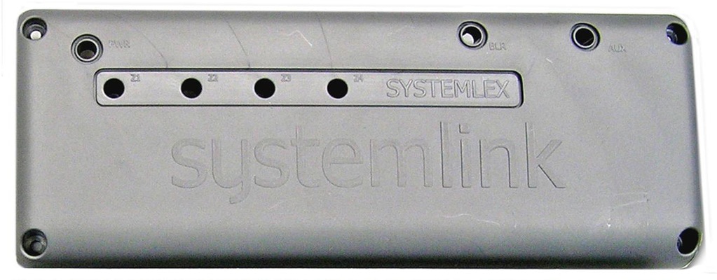
With the light at the beginning middle and end a 3 way dimmer multiple lights controlling a receptacle and troubleshooting tips. Systemlex links all the electrical components in a simple and efficient way. The power can come from either the switch box or the fixture box and a set of electrical switch wiring diagrams will explain each of these scenarios to you clearly. Systemlink systemlex large zone wiring centre. 1 greenhills business park greenhills road tallaght dublin 24. Built in led for boiler or zone indication or fault finding.
See how the anti. Systemlex is designed for up to. 353 1 4031200 contact us today. Switch wiring diagrams a single switch provides switching from one location only. For bulk orders please ring systemlink technology offices on 01 403 1200. A pre configured wiring centre for controlling heating zones.
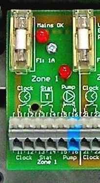
3a typical wiring scheme for single zone ufh system with a system boiler s plan wiring centre s plan wiring centre section a 2a. All installations should be undertaken by a qualified person only. Systemlex does all the complicated cross wiring for the installer all that is left is to connect the centre to the board. Wiring diagrams for 3 way switches diagrams for 3 way switch circuits including. All connections are numbered for foolproof installation. Systemlex does the rest.
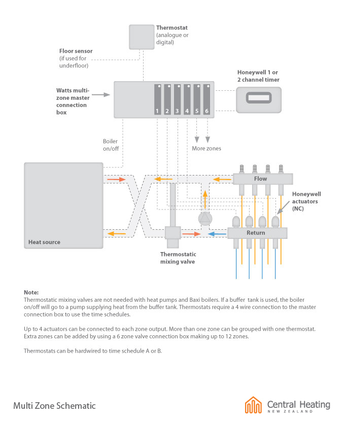
Typical wiring scheme for multi zone uhf system with a system boiler this drawing is for guidance only.
