Before starting the system turn the volt and stab trimmers fully anticlockwise and the amp and hz trimmers fully clockwise. The terminal block and avr automatic voltage regulator are in the box above the generator.

5ceb55 Sr7 Voltage Regulator Wiring Diagram Wiring Resources
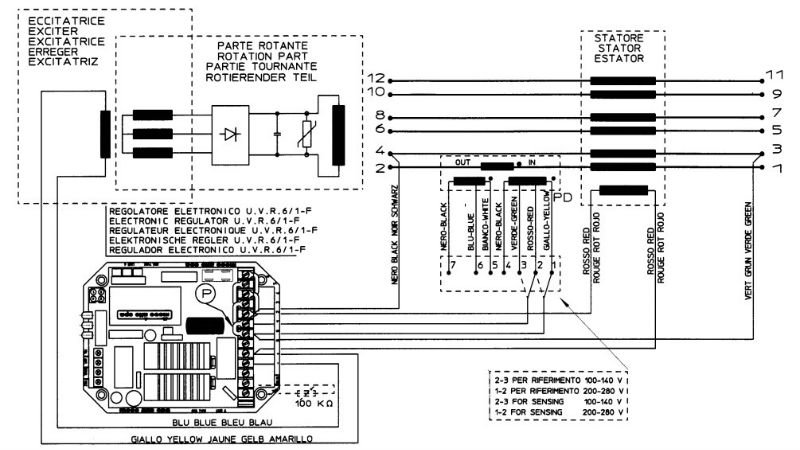
Sr7 avr wiring diagram. In the photo of the terminal block shown above observe that each of the terminals has a blue collar with numbers printed in white. Most important and practical aspects of the sr72 elec tronic regulator. Generator circuit diagram avr sr7 2 automatic ac voltage stabilizer factory price find complete details about generator circuit diagram avr sr7 2 automatic ac voltage stabilizer factory priceavr sr7 2automatic ac voltage stabilizergenerator circuit diagram avr from generator parts accessories supplier or manufacturer fuan vision machinery electric co ltd. It guarantees alternator self excitation from a speed equal to zero up to nominal speed. 132 machine test procedure sr7 the regulator should be connected as shown in the relevant diagram in figure 7. Setting it apart from the rest the sr7 2g has a unique feature that enables superb stabilizing by the turn of the pot.
The scc006202 diagram shows the connection to 12 terminal alternators with reference to half phase from 70v to 140v. With the latest technology in power regulation this automatic voltage regulator can support voltage regulation starting from eco28 to eco32 generator ends. Connect a light between the generator phase and. The scc006302 diagram shows the connection to 12 terminal alternators for connec tions in series star or series delta with reference to the entire phase from 140v to 280v. The numbers indicate the number of each terminal corresponding to the numbers in the diagrams on the following pages. The starting block is a circuit that opera tes with the residue voltage of the alternator v5vac and which produces a voltage impulse to self excite the alternator.
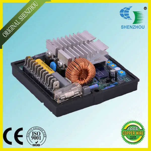
The avr sr7 2g are generally used on eco32 generator ends.


