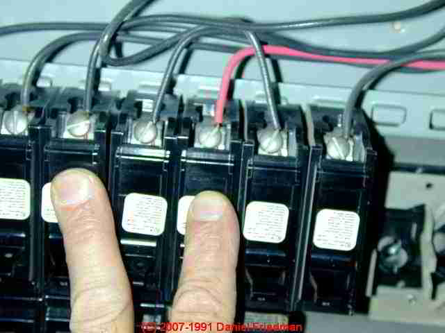
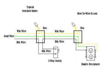
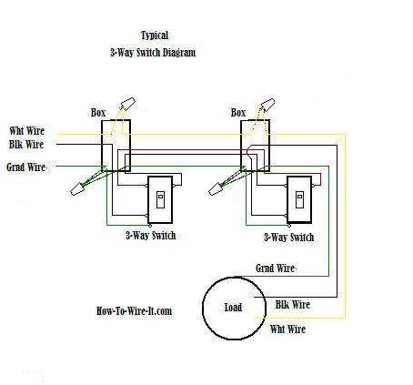
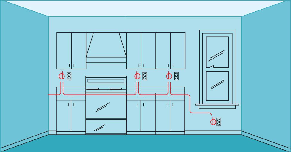
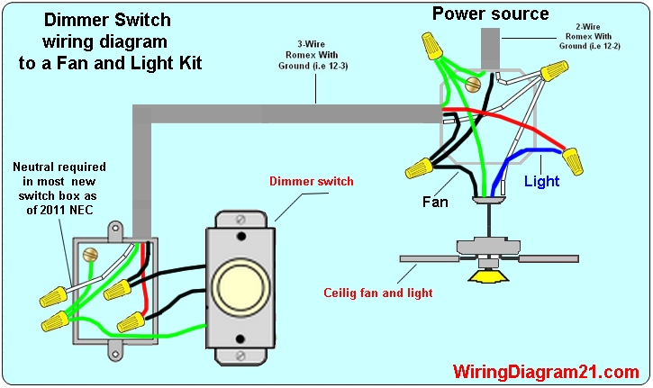
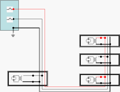
This photo is an example of a multiwire branch circuit incorrect wiring diagram. Therefore the total neutral current is the vector sum of the three line currents.
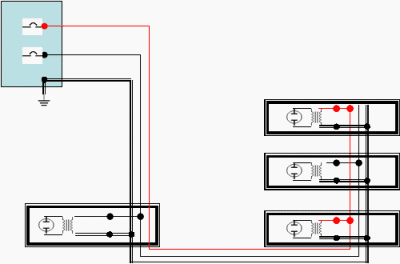
Potential Neutral Conductor Hazards Rf Cafe
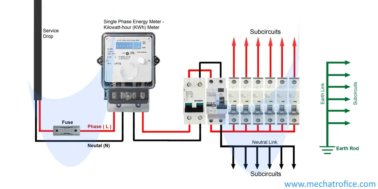
Shared neutral wiring diagram. In the above diagram the alternator is connected to the load by three phase four wire system. Multiwire branch circuits can offer fewer conductors reduce the raceway size and reduce voltage drop. In a 3 phase system it is legal in some jurisdictions to share a single neutral wire between all three 3 phases. The neutral wire serves as common return to all the three phases acting outward from n 1. A shared neutral circuit uses 3 conductor nm b wire to join two adjacent circuit breakers in the panel to a junction box near the branch circuit loadsoutlets see figure 2. David berquist 688 views.
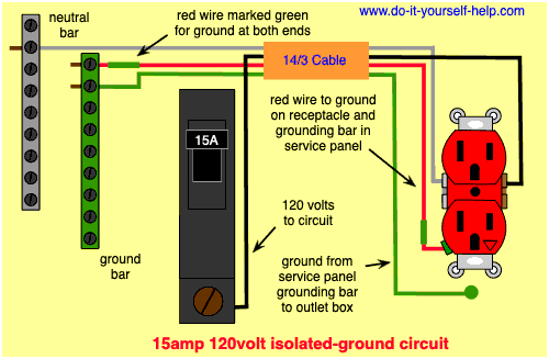
This photo is an example of a multiwire branch circuit preferred wiring diagram. I show and explain a shared neutral 2 separate circuits wiring a outlet 2 circuits in 1 outlet duration. The use of shared neutral circuits produces significant copper savings when two branch circuits are close to each other but far from the circuit breaker panel. A shared neutral is a connection in which a plurality of circuits use the same neutral connection. The neutral points in both alternator and the load are joined together. This is also known as a common neutral and the circuits and neutral together are sometimes referred to as an edison circuit.
These can often be found in older properties where the stairway light is connected to line from the. Shared or borrowed neutrals which are unwanted interconnections between two circuits. Why are multiwire branch circuits used.

