The dpst contacts switch when the button is depressed and return when it is released. Single door controlled egress wiring diagram 01 single door digital entry wiring diagram 10 single door dk 26 with door prop alarm wiring diagram 15 single door dk1 11 xms dt 7 wiring diagram 20 single door dk 26 remote release wiring diagram 14 single door dk 26 unl 24 and dt 7 wiring diagram 18 single door dk 26 using the hard code to toggle lock off and on wiring diagram.
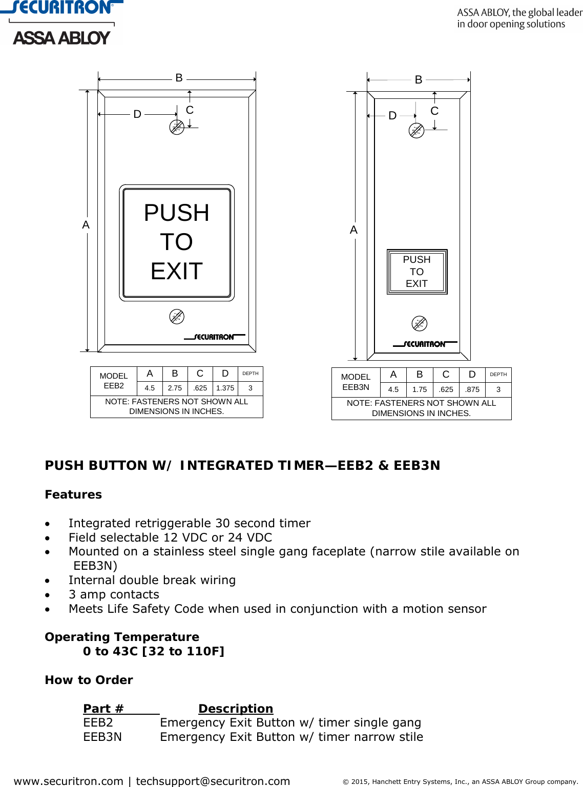
Securitron Eeb Spec Eeb2 Eeb3n Architectural Specifications Eeb2
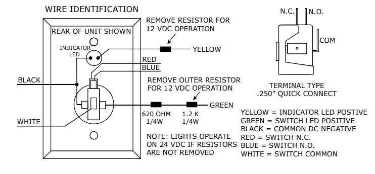
Securitron push to exit button wiring diagram. Both eeb2 and eeb3n have a 3a switching. Double break wiring between the exit button electric lock and dk 12. The exit button must have normally open and normally closed contacts and be of the dpdt type. Remote push button with electric latch retraction fire rated application. Securitrons ul294 certification indicates that when the eeb is used with the xms motion sensor it meets the nfpa life safety code 101 requirements for exit of access controlled egress doors. Wiring instructions fail secure strike with one button power supply push button no fail secure strike polarity insensitive depressing the push button would close the circui t allow power to flow and release the strike.
Through hole mounting design. Wires and a typical wiring diagram showing a power supply motion detector push button and magnalock so as to comply with the boca code for access controlled egress doors. Model eeb3n is a rectangular exit button mounted on a 1 34 ss. Wcc and wbb available for all single gang push buttons keyswitches and keypads. Both the push button contacts and the internal timer relay contacts are in series with the white and green wires. Electric latch retraction with auto operator.
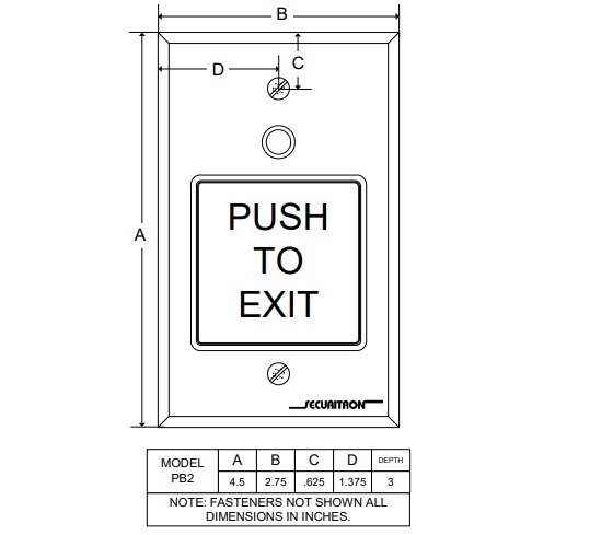
Note that you should always consult your local building department when securing doors that are part of an. Riser diagrams falcon exit devices. One single door with panic bar. 120896 5900 x 24vdc fail secure strike. Securitron eeb2 eeb3n exit button with integrated timer installation and operating instructions description model eeb2 is a two inch square exit button mounted on a stainless steel ss single gang key plate. Description the model pb5 is a spring loaded momentary 2 diameter illuminated exit button mounted on a stainless steel single gang outlet box cover.
Narrow stile key plate. Securitron pb5 exit button installation and operating instructions 1. The following common wiring diagrams are available. The red and white wires from the eeb23n must receive voltage from the same power supply. Power supply may be ac or dc depending on the requirements of the strike. Exit buttons that fit this need are available from securitron.
There is a point to note about the internal design of the unit. This can be accomplished with any of securitrons push buttons and the model tm 8l timer. Identification of the wires and a typical wiring diagram showing a power supply motion detector push button and magnalock so as to comply with the boca code for access controlled egress doors. Both the push button contacts and.
