View and download honeywell rth111 user manual online. Do not use b wire if you already have o wire.

Honeywell Rth111b1024 Quick Installation Guide Free Pdf
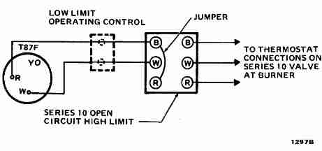
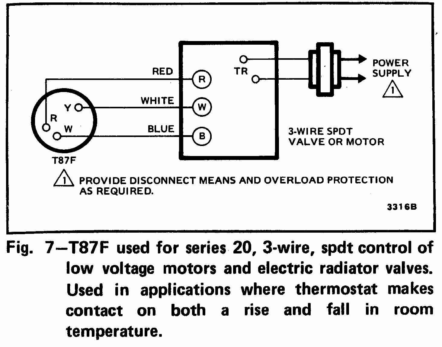
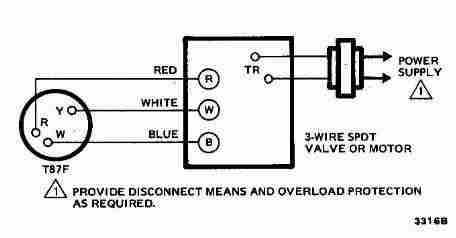
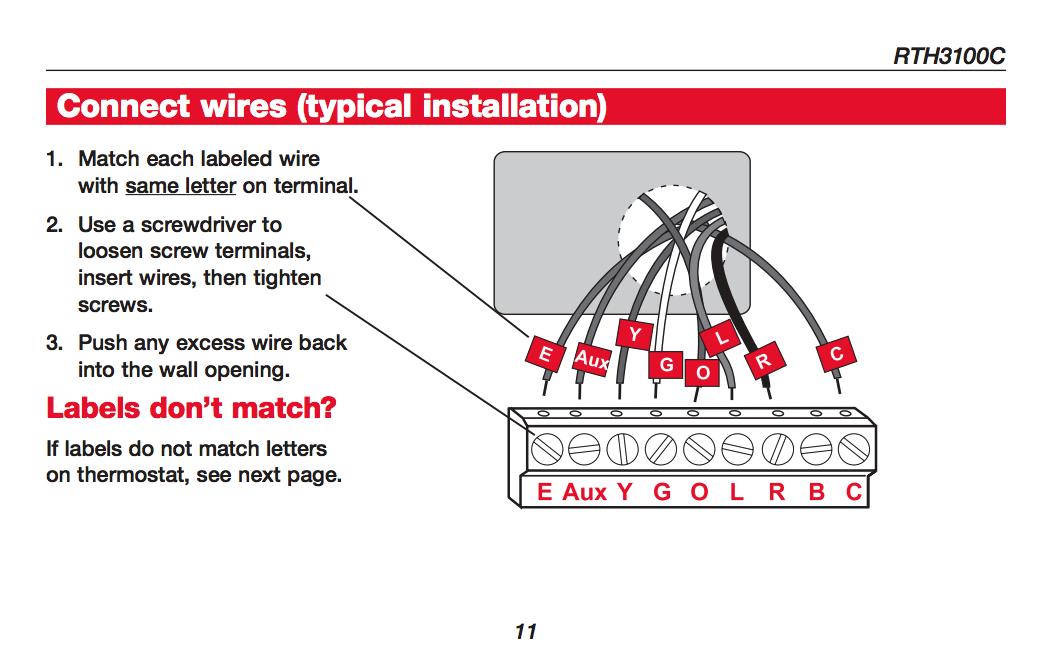
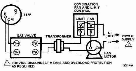
Rth111b1024 u1 wiring diagram. 5 connect wires alternate wiring if labeled wire does not match any terminal designation see diagram below. When replacing an existing thermostat simply note the terminals to which the wires are attached and attach them to the same terminals. M32169a remove jumper between r and rc if you have wires on both r and rc. Wrap bare end of wire with electrical tape. Alternate wiring quick installation guide connect wires contd alternate wiring if a labeled wire does not match any terminal designation see diagram below. Digital non programmable thermostat rth111b1024 read user manual online or download in pdf format.
Just set it to the temperature you want and adjust it up or down as desired. Do not use c c1 or x wire. For more than a century honeywell thermostats have been the popular choice of homeowners. Do not use c c1 or x wire. See pages 1517 to change function settings. Rth111 thermostat pdf manual download.
From smart wifi thermostats with room sensors and humidification control to programmable and non programmable thermostats resideo products meet a variety of needs. Do not use b wire if you already have 0 wire. Wrap bare end of wire with electrical tape. Do not use b wire if you already have o wire. R rc rh 4 and v. Do not use c c1 or x wire.
Place a jumper piece of wire between y and. If its a new installation you may have to identify the wires first. Wiring assistance troubleshooting 5 5 m32768 system setup note. Alternate wiring if a labeled wire does not match any terminal designation see diagram below. If you do not press any button for 60 seconds while you are in the setup menu the thermostat automatically saves any changes made and exits the menu. The honeywell rth111b is a programmable version of the honeywell rth111 thermostat series.
A non programmable thermostat provides simple control of your heating and cooling system. 3ø wiring diagrams 1ø wiring diagrams diagram er9 m 3 1 5 9 3 7 11 low speed high speed u1 v1 w1 w2 u2 v2 tk tk thermal overloads two speed stardelta motor switch m 3 0 10v 20v 415v ac 4 20ma outp uts diagram ic2 m 1 240v ac 0 10v outp ut diagram ic3 m 1 0 10v 4 20ma 240v ac outp uts these diagrams are current at the time of publication. Press the s or t button to change the setting. Wrap bare end of wire with electrical tape. This thermostat cannot be used if your old thermostat had any two of the following wires.
